Motor Vehicle Lift Control System

a technology for controlling systems and motor vehicles, applied in the direction of pedestrian/occupant safety arrangements, cycle equipment, instruments, etc., can solve the problems of significant danger wheelie occurs when the front of the vehicle is lifted off the ground, and significant risks to the pilot of the vehicl

Inactive Publication Date: 2014-09-18
HOOKWAY DONALD WILLIAM +1
View PDF6 Cites 6 Cited by
  • Summary
  • Abstract
  • Description
  • Claims
  • Application Information

AI Technical Summary

Problems solved by technology

This fact has since spawned a subgroup of motorized vehicles which are not built primarily for efficient and quick transportation, but instead to simply go as fast as possible.
Whenever a high performance vehicle is piloted at high speeds, there are significant risks to the pilot of that vehicle, particularly under certain conditions.
One such condition that can put the vehicle pilot in significant danger is known as a wheelie.
A wheelie occurs when the front of the vehicle lifts off the ground as a result of the excessive amounts of torque on the rear axle of the motor vehicle.
Though impressive and exciting to behold, wheelies can be dangerous to the pilot of the motor vehicle for several reasons.
Firstly, the pilot is largely unable to steer the vehicle when the front wheel or wheels are off the ground.
This can make it very easy to lose control of the motor vehicle and careen off the race track at a high speed.
Secondly, the pilot can sometimes apply such an excessive amount of torque that the vehicle continues to spin backwards eventually either flipping over entirely or damaging the rear of the vehicle.
Unfortunately, these safety devices are manually triggered, relying on the pilot of the vehicle to trigger the safety device if it becomes necessary.
In some cases, the pilot may not be able to react fast enough, or they may make a poor judgment call and fail to activate the safety device soon enough to prevent a disaster.

Method used


Image

  • Motor Vehicle Lift Control System
  • Motor Vehicle Lift Control System
  • Motor Vehicle Lift Control System

Examples


Embodiment Construction

[0016]All illustrations of the drawings are for the purpose of describing selected versions of the present invention and are not intended to limit the scope of the present invention.

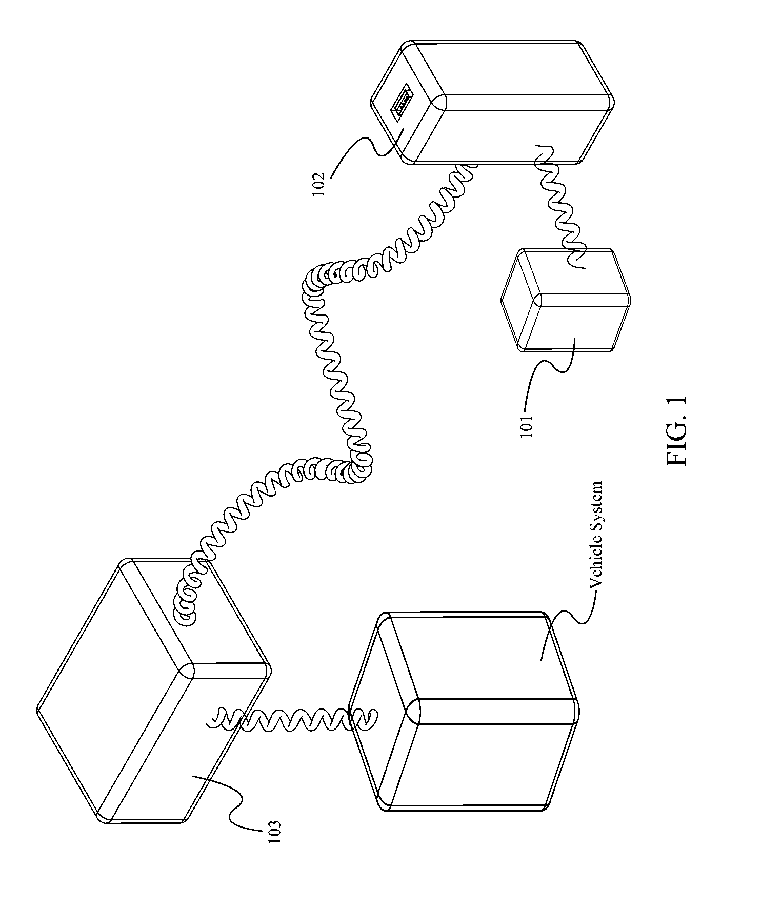
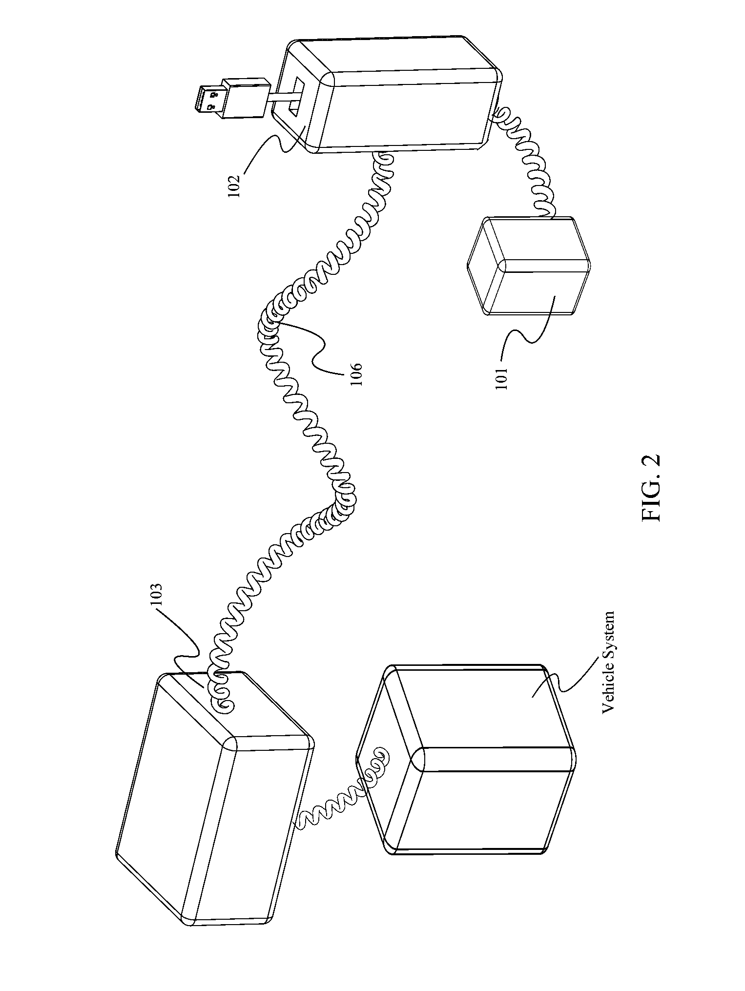
[0017]The present invention is an automatic motor vehicle lift control system. It comprises a few functional components which interact with one another in specific ways, thus forming the system of the present invention.

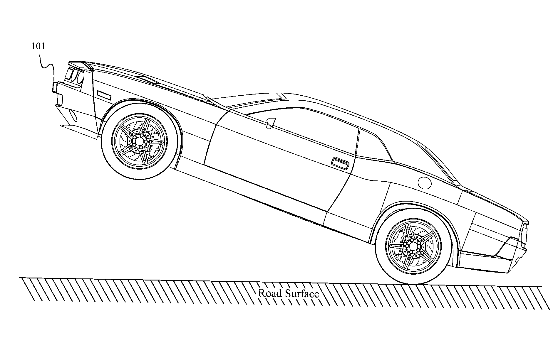
[0018]This automatic motor vehicle lift control system includes a sensor 101, which provide sensor inputs, a cpu (central processing unit) 102, a control actuator 103, which provides control outputs to the vehicle, and a user interface 104. It operates upon certain parameters which are entered into the system via the user interface. The parameters define physical values which represent the operational characteristics of the system, the distance of the front of the motor vehicle from the operating surface, or the angle of the vehicle relative to downward gravitational forces. The sensor(s) ...


PUM


Abstract

An automatic motor vehicle lift control system responds to a motor vehicle wheelie event when a motor vehicle front lifts off from an operating surface. It functions to reduce power output from an engine of a vehicle in wheelie to prevent an accident. This automatic motor vehicle lift control system includes a number of functional components including sensor, central processing unit (cpu), control actuator and user interface. The sensor may be mounted on an external location of a vehicle. It functions to gather information of a physical state of a motor vehicle and then send it to the cpu for processing. The cpu receives input from the sensor and the user interface, as well as conduct processing and determination. The control actuator received order from the cpu and then act on the vehicle to avoid a wheelie accident.

Description

[0001]The current application claims a priority to the U.S. Provisional Patent Application Ser. No. 61 / 802,859, filed on Mar. 18, 2013.FIELD OF THE INVENTION[0002]The present invention relates generally to motorized vehicles. More specifically it is a motorized vehicle lift control system which helps to prevent flipping over during driving.BACKGROUND OF THE INVENTION[0003]Throughout history, humankind has always sought a method of faster travel. The advent of motorized vehicles has allowed people to travel over great distances in a quite short period of time. Motorized ships, cars, and planes, were all developed to allow for much faster transport of both trade goods and people. Although motorized vehicles were developed originally to serve as transportation from one location to another, they were designed to do so at an increased speed when compared with other methods. This fact has since spawned a subgroup of motorized vehicles which are not built primarily for efficient and quick ...

Claims


Application Information

Patent Timeline
Patent Type & Authority Applications(United States)
IPC IPC(8): B60R21/0132
CPCB62J27/00B60W40/10B60W10/06B60W30/188B60W2520/16B60W2710/0616B60W2710/0644
Inventor HOOKWAY, DONALD WILLIAMHOOKWAY, III, WILLIAM C.
Owner HOOKWAY DONALD WILLIAM
Why Eureka
Try Eureka