Dual feed hydraulic lash adjuster for valve actuating mechanism

a technology of hydraulic lash adjuster and valve actuating mechanism, which is applied in the direction of valve arrangement, mechanical equipment, machines/engines, etc., can solve the problems of one-piece plunger body, no separate fluid pressure separator, and the description of dual feed hydraulic lash adjuster suffers

Active Publication Date: 2014-09-25
GT TECH INC
View PDF2 Cites 12 Cited by
  • Summary
  • Abstract
  • Description
  • Claims
  • Application Information

AI Technical Summary

Benefits of technology

The present invention provides a new type of hydraulic lash adjuster for use in engines. This adjustor has two ways it can get oil: through its own system or by sharing some of the main system's oil. It also has extra space to remove any air bubbles before sending out the oil. Additionally, this adjustor has special channels and passages designed to make sure the oil flows properly throughout the whole machine. Overall, this design helps improve how oxygen sensors work in these engines, which makes them more efficient and reliable.

Problems solved by technology

This patent discusses the issue of traditional hydraulic lash adjusters used in valve actuating mechanisms for internal combustion engines. These mechanisms require a minimum level of hydraulic fluid pressure to operate, but they often result in slow response times due to the limited availability of oil. Dual feed hydraulic lash adjusters offer a solution by allowing for more efficient lubricant delivery and improved performance. However, existing solutions still suffer from drawbacks like lack of separators and inflexible design options. Therefore, the technical problem addressed in this patent is how to create a better double feed hydraulic lash adjuster with improved features like separators and flexibility.

Method used


Image

  • Dual feed hydraulic lash adjuster for valve actuating mechanism
  • Dual feed hydraulic lash adjuster for valve actuating mechanism
  • Dual feed hydraulic lash adjuster for valve actuating mechanism

Examples


Embodiment Construction

)

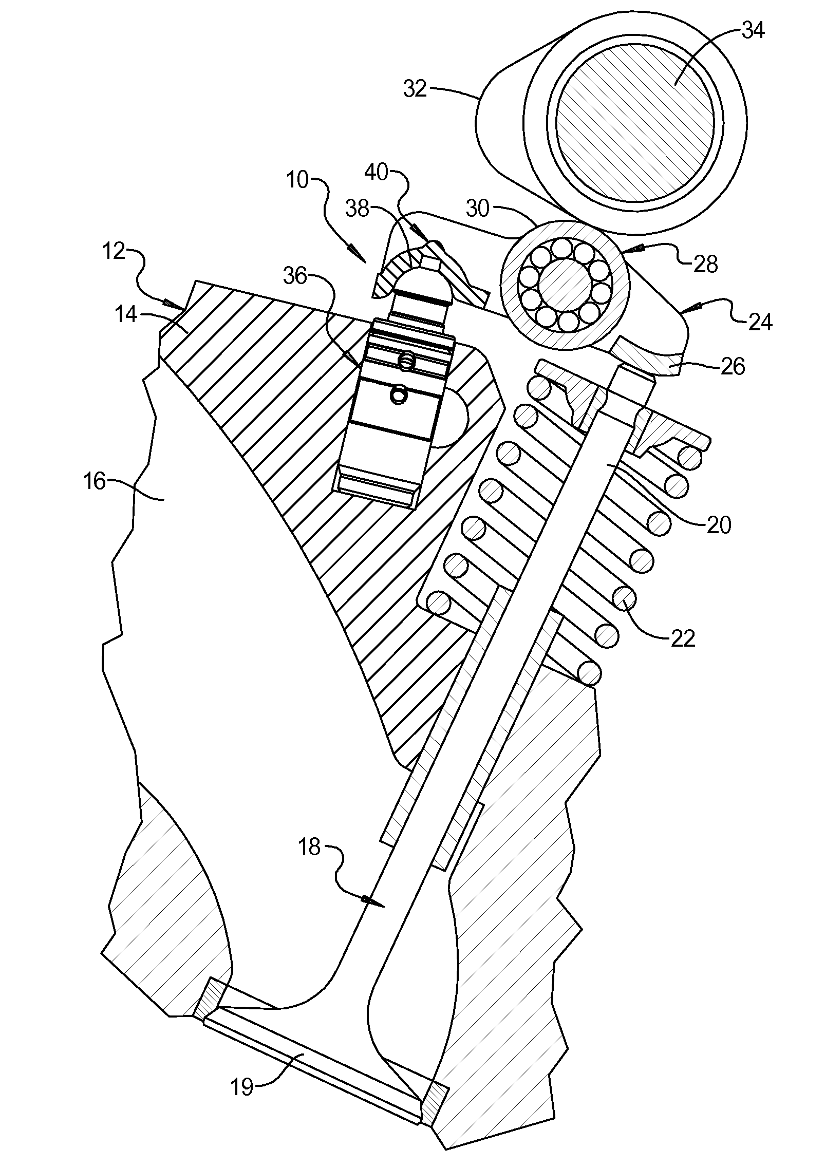
[0024]Referring now to the drawings, and in particular FIG. 1, one embodiment of a valve actuating mechanism 10 of a finger follower type is shown for an internal combustion engine, generally indicated at 12. The engine 12 is of an overhead cam type having a cylinder head 14 including an inlet or exhaust port 16. The engine 12 also includes a valve 18 having a head 19 and a stem 20 extending from the head 19. The engine 12 includes a spring 22 disposed about the stem 20 that biases the head 19 of the valve 18 to a closed position. The valve actuating mechanism 10 also includes a finger follower, generally indicated at 24, having a pallet or actuating pad 26 engaging the stem 20 of the valve 18. The valve actuating mechanism 10 further includes a roller cam follower 28 having an outer surface 30 engaged by an associated cam 32 of a camshaft 34.

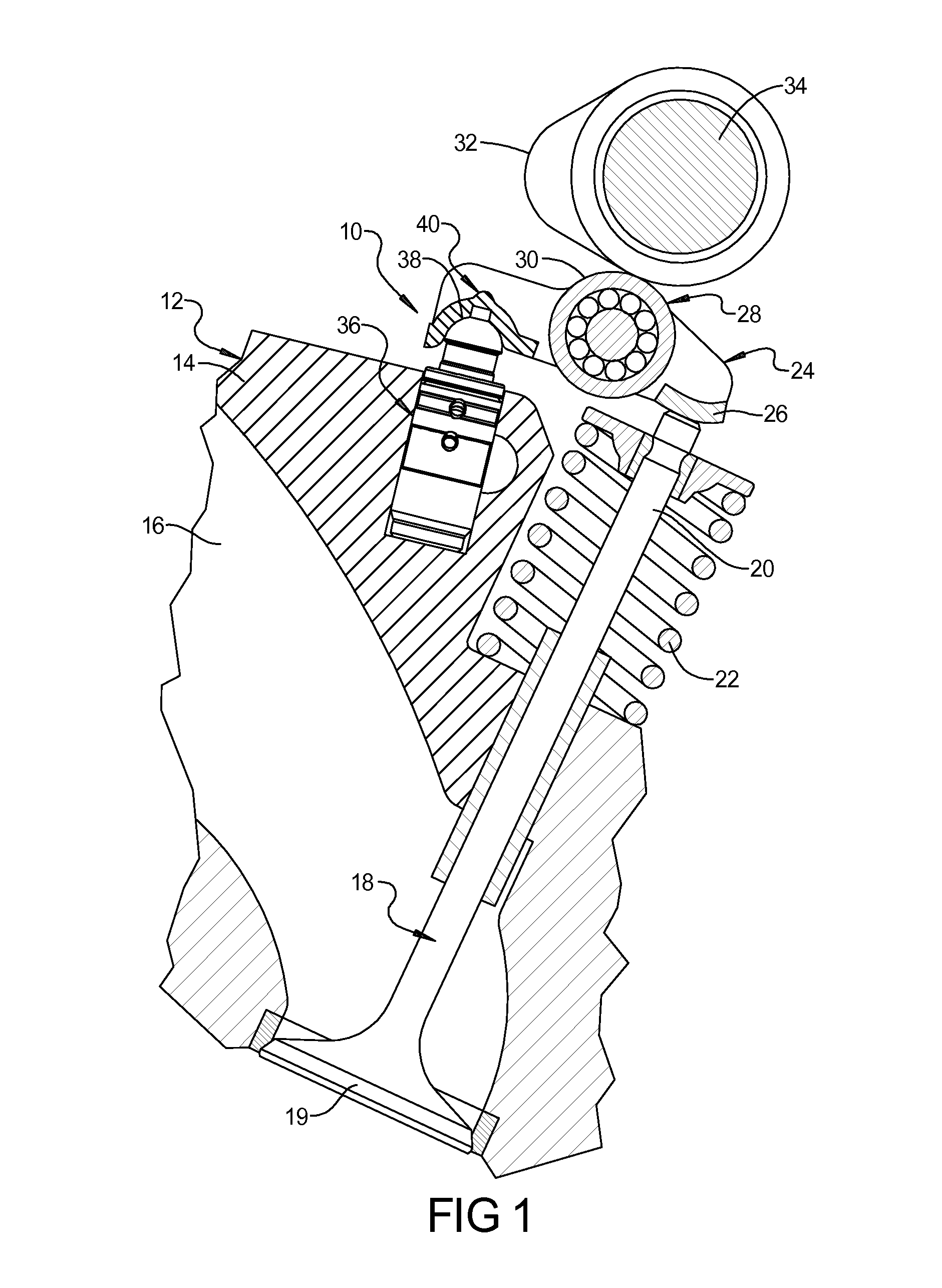
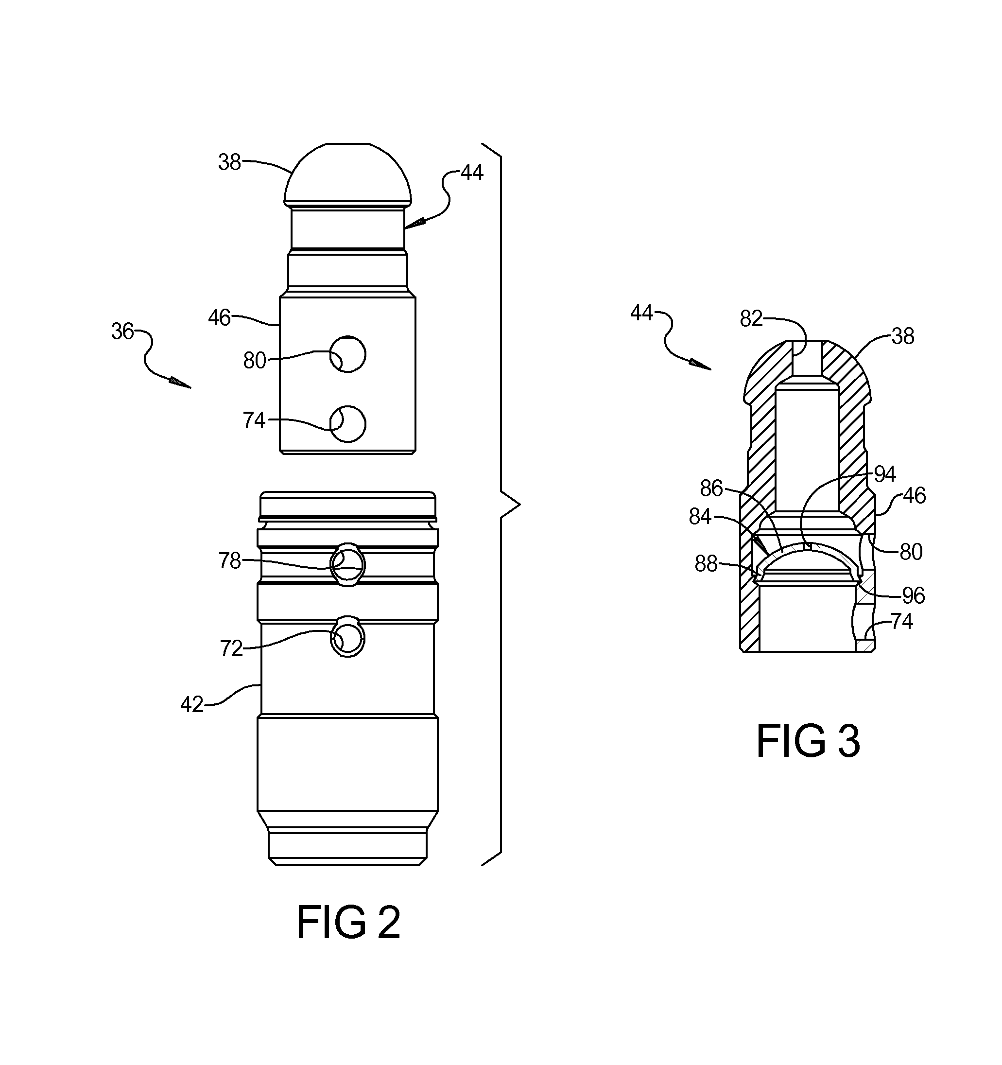
[0025]A dual feed hydraulic lash adjuster, according to the present invention and generally indicated at 36, is supported by the cylinder hea...


PUM


Abstract

A dual feed hydraulic lash adjuster includes a plunger assembly slidingly disposed in a lash adjuster body and having an end adapted to cooperate with a valve actuating mechanism, the plunger assembly forming a low-pressure first chamber and a high-pressure second chamber with the body, the plunger assembly having a first aperture fluidly communicating with the first chamber, a passageway fluidly communicating with the first chamber, and a second aperture fluidly communicating with the passageway, and a separate fluid pressure separator disposed in the plunger assembly between the first aperture and the second aperture to prevent passage of hydraulic fluid between the first chamber and the passageway, wherein a passage is provided through the fluid pressure separator to provide for evacuation of air from the lash adjuster.

Description


Claims


Application Information

Patent Timeline
Owner GT TECH INC
Why Eureka
Try Eureka