Power-on circuit

Inactive Publication Date: 2014-09-25
HONG FU JIN PRECISION IND (SHENZHEN) CO LTD +1
View PDF17 Cites 4 Cited by
  • Summary
  • Abstract
  • Description
  • Claims
  • Application Information

AI Technical Summary

Problems solved by technology

When one wants to power-on the desktop computer, one needs to b

Method used


Image

  • Power-on circuit
  • Power-on circuit

Examples


Embodiment Construction

[0008]The disclosure, including the drawing, is illustrated by way of example and not by way of limitation. References to “an” or “one” embodiment in this disclosure are not necessarily to the same embodiment, and such references mean at least one.

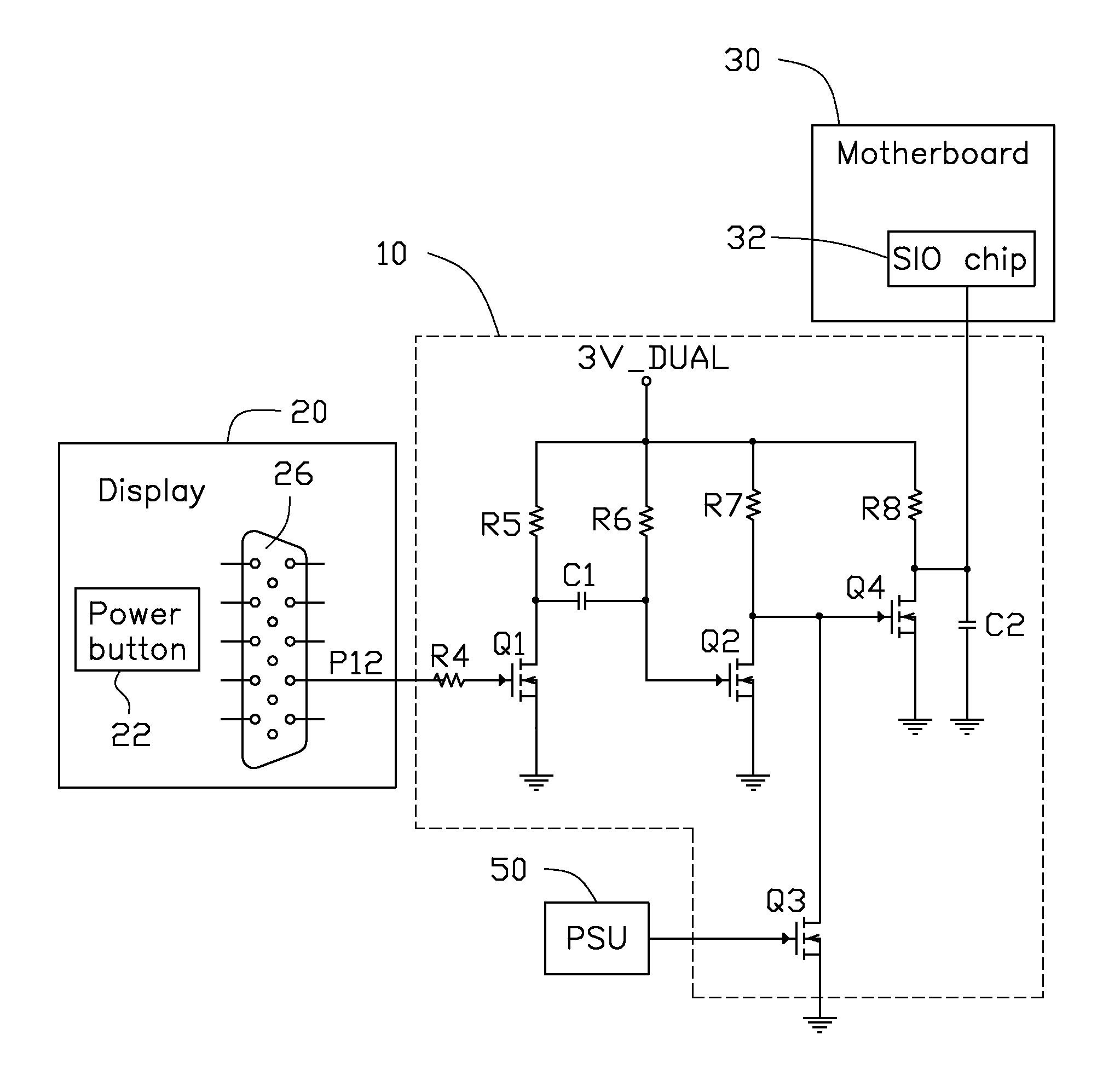
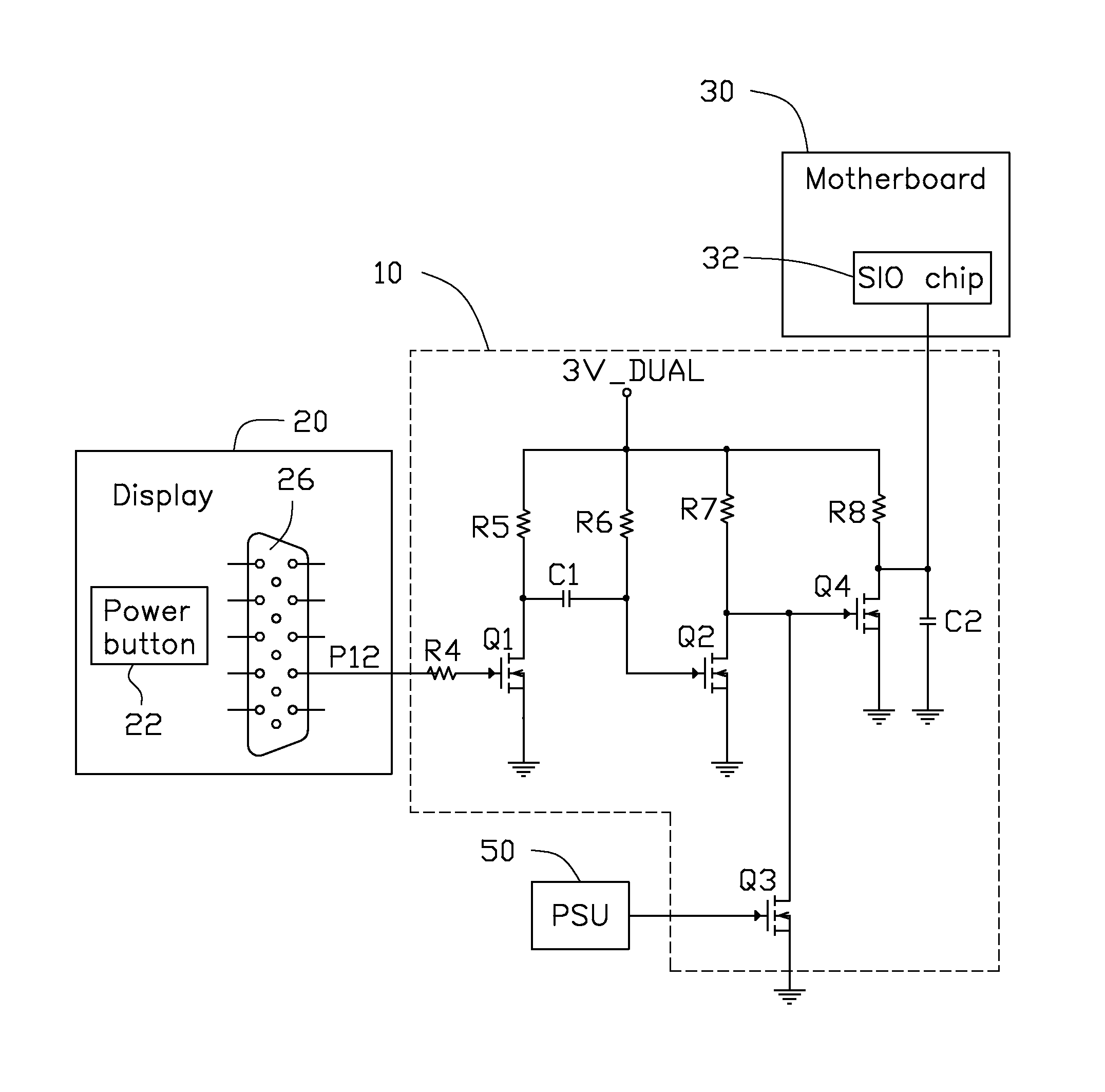
[0009]The FIGURE shows an embodiment of the present disclosure of a power-on circuit 10. The power-on circuit 10 is connected to a display 20, a motherboard 30, and a power supply unit (PSU) 50. The power-on circuit 10 includes two capacitors C1 and C2, four electronic switches Q1-Q4, and five resistors R4-R8. The display 20 includes a power button 22 and a 15-pin video graphics array (VGA) connector 26. The motherboard 30 includes a super input output (SIO) chip 32.

[0010]Each of the electronic switches Q1-Q4 includes a first terminal, a second terminal, and a third terminal. The first terminal of the electronic switch Q1 is connected to a serial data line (SDA) pin P12 (namely the twelfth pin) of the VGA connector 26 through the resistor ...


PUM


Abstract

A power-on circuit is connected to a video graphics array (VGA) connector of a display, a power supply unit (PSU), and a super input output (SIO) chip of a motherboard. The power-on circuit includes first to fourth electronic switches. The VGA connector is connected to the first electronic switch. The first electronic switch is connected to the second electronic switch. The second electronic switch is respectively connected to the third electronic switch and the fourth electronic switch. The fourth electronic switch is connected to the SIO chip. The power-on circuit could power on the motherboard via the power button on the display.

Description

BACKGROUND[0001]1. Technical Field[0002]The present disclosure relates to a power-on circuit.[0003]2. Description of Related Art[0004]Most desktop computers include a power button on a front panel of a chassis. However, most chassis are generally placed under computer desks. When one wants to power-on the desktop computer, one needs to bend over to press the power button, which is very inconvenient.[0005]Therefore, there is room for improvement in the art.BRIEF DESCRIPTION OF THE DRAWING[0006]Many aspects of the present disclosure can be better understood with reference to the following drawing. The components in the drawing are not necessarily drawn to scale, the emphasis instead being placed upon clearly illustrating the principles of the present disclosure. Moreover, in the drawing, like reference numerals designate corresponding parts throughout the several views.[0007]The FIGURE is a circuit diagram of a power-on circuit, in accordance with an embodiment of the present disclosu...

Claims


Application Information

Patent Timeline
IPC IPC(8): H03K17/22
CPCH03K17/22G06F1/26G09G5/006G09G2300/0426G09G2330/022
Inventor ZHOU, HAI-QING
Owner HONG FU JIN PRECISION IND (SHENZHEN) CO LTD
Why Eureka
Try Eureka