
Computing I/Q Impairments at System Output Based on I/Q Impairments at System Input

a technology of impairment and system output, applied in the field of signal processing, can solve problems such as potential skew of constellation diagram or artificial noise floor, different phase displacements of i/q channels, and different gains of i channel and q channels, and achieve the effect of reducing the probability of i/q impairmen

Active Publication Date: 2014-09-25
NATIONAL INSTRUMENTS
View PDF1 Cites 17 Cited by
  • Summary
  • Abstract
  • Description
  • Claims
  • Application Information

AI Technical Summary

Benefits of technology

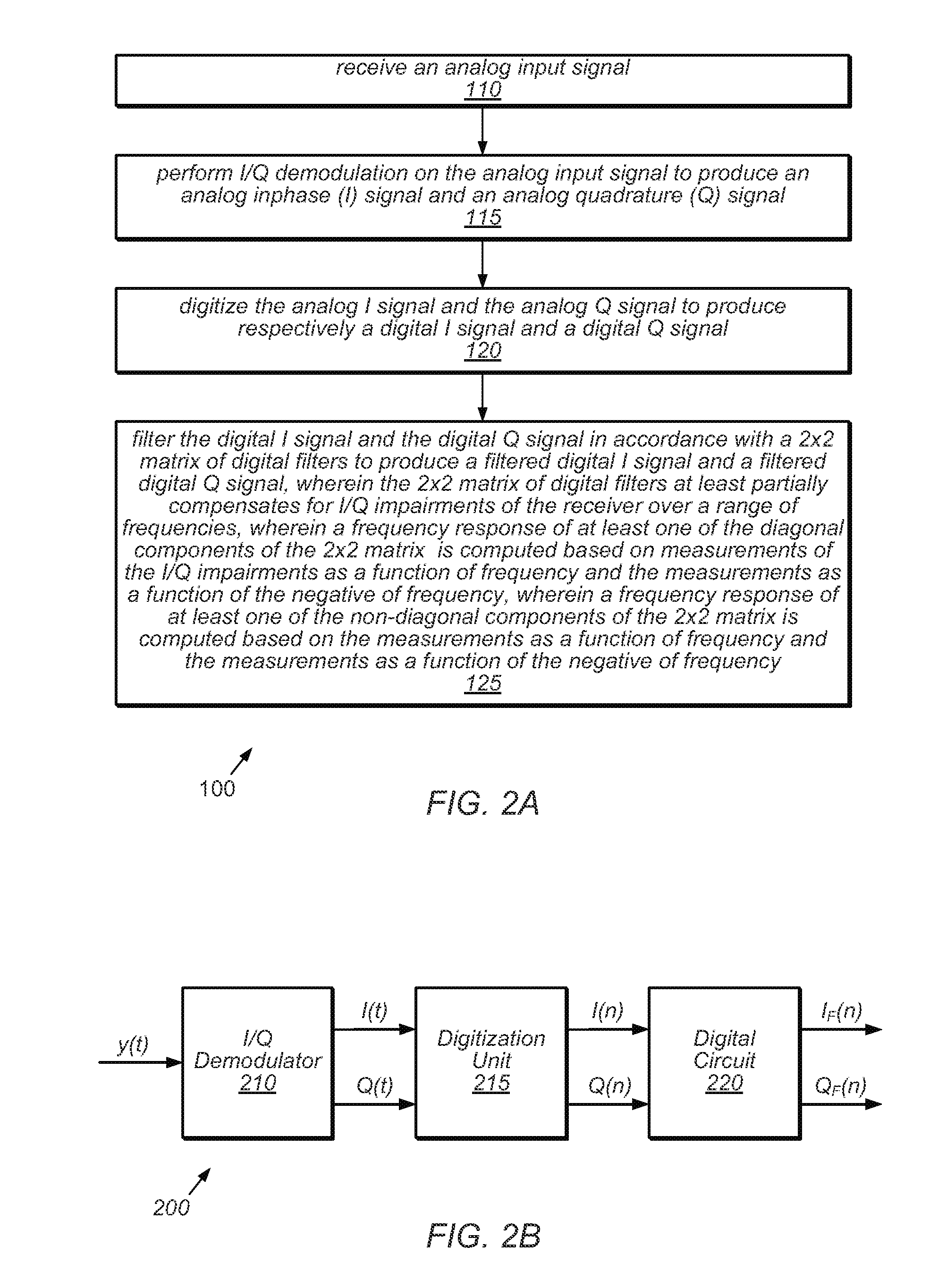
The patent describes methods for reducing impairments in signals used by communication devices. The methods involve receiving a transmission signal, performing demodulation and conversion to produce digital signals, and then applying wideband correction to the signals to compensate for frequency-dependent variations in gain and phase imbalance. This helps to improve the accuracy of the signals and enhance the performance of communication devices.

Problems solved by technology

In reality, however, I / Q impairments in the transmitter will cause the I channel and Q channel to have different gains and different phase displacements.
Such distortions imply among other things that the transmitted signal will have unwanted energy at a frequency equal to the negative of the tone frequency.
Depending on the communication standard, this unwanted “image” results in potential skew on the constellation diagram or an artificial noise floor.
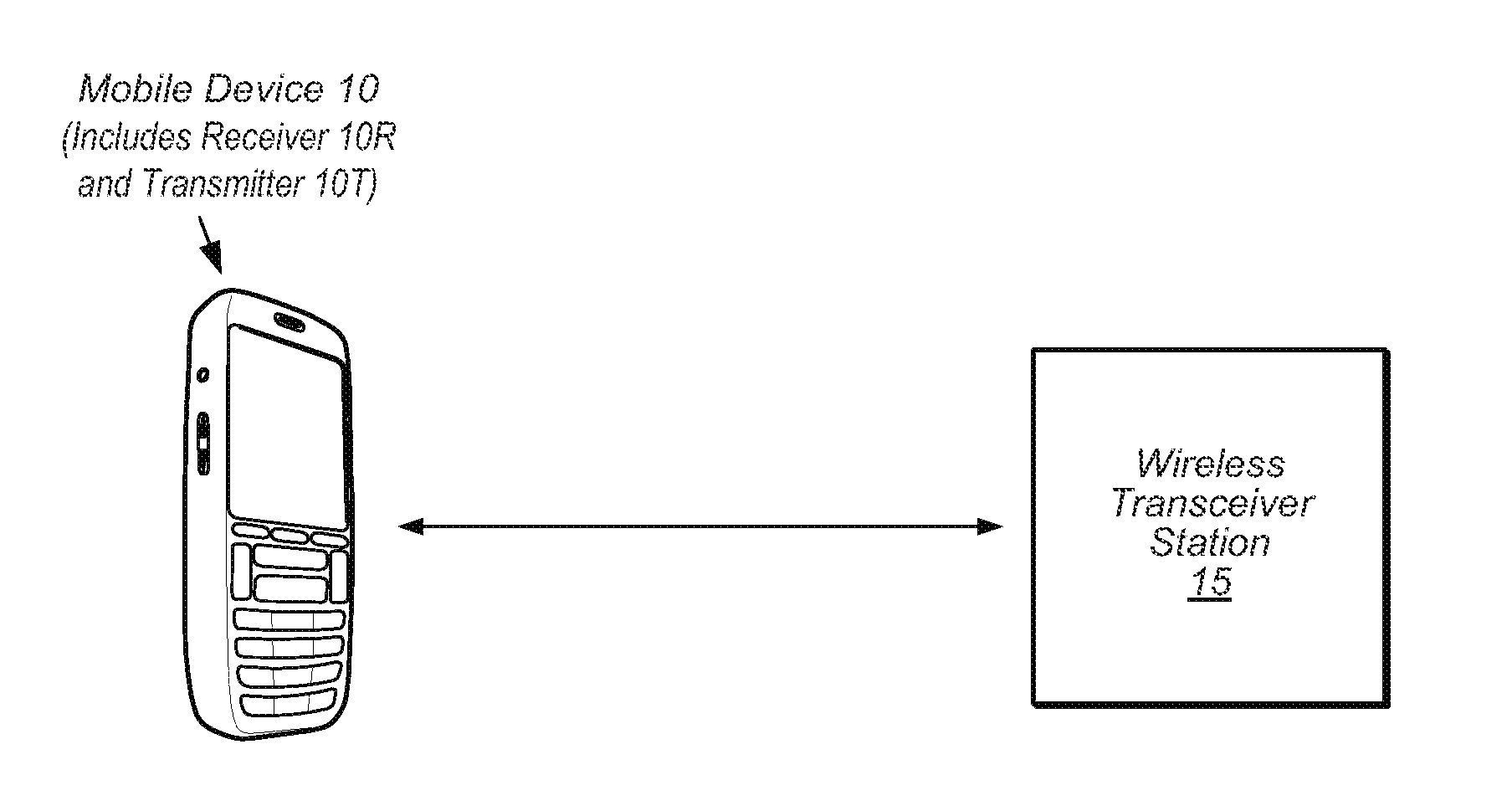
Receivers have a similar problem.
When a receiver is stimulated with a pure tone at frequency f, the complex signal appearing at the output of the receiver's I / Q demodulator will include unwanted signal energy at frequency −f in addition to energy at frequency f. In both case (transmitter and receiver), the difficulty arises due to imbalances in gain and phase between the I channel and the Q channel.
However, quality measurements may be difficult to obtain.
However, the receiver's I / Q demodulator corrupts the estimates with its own I / Q impairments.
Furthermore, the signal path between the transmitter's I / Q modulator and the receiver's I / Q demodulator also introduces distortion to the estimates.
The gain imbalance and the phase skew at the complex input of the electrical system may represent a gain imbalance and a phase skew at the input (or alternatively, at the output) of the demodulator.
The gain imbalance and the phase skew at the complex output of the electrical system may represent a gain imbalance and a phase skew at the output of the I / Q modulator.

Method used


Image

  • Computing I/Q Impairments at System Output Based on I/Q Impairments at System Input
  • Computing I/Q Impairments at System Output Based on I/Q Impairments at System Input
  • Computing I/Q Impairments at System Output Based on I/Q Impairments at System Input

Examples


case 1

[0319] Odd Phase Skew

[0320]In the case of odd phase skew, i.e., φ(f)=φ1(f)=−φ2(f) for f>0, equations (1.20) through (1.23) specialize to:

A(f)=0  (1.24)

EB(f)={g2(f)−g1(f)} / {g1(f)+g2(f)}  (1.25)

C(f)=2 cos(φ(f)) / {g1(f)+g2(f)}  (1.26)

ED(f)=2 sin(φ(f)) / {g1(f)+g2(f)}.  (1.27)

case 2

[0321] Even Gain Imbalance

[0322]In the case of even gain imbalance, i.e., g(f)=g1(f)=g2(f) for f>0, equations (1.20) through (1.23) specialize to:

A(f)=-sin(ϕ1(f)+ϕ2(f))1+cos(ϕ1(f)+ϕ2(f))(1.28)EB(f)=0(1.29)C(f)=cos(ϕ1(f))+cos(ϕ2(f))g(f){1+cos(ϕ1(f)+ϕ2(f))}(1.30)ED(f)=sin(ϕ1(f))-sin(ϕ2(f))g(f){1+cos(ϕ1(f)+ϕ2(f))}.(1.31)

case 3

[0323] Odd Phase Skew and Even Gain Imbalance

[0324]In the case of odd phase skew and even gain imbalance, equations (1.20) through (1.23) specialize to:

A(f)=0  (1.32)

EB(f)=0  (1.33)

C(f)=cos(φ(f)) / g(f)  (1.34)

ED(f)=sin(φ(f)) / g(f).  (1.35)


PUM


Abstract

Systems and methods for measuring transmitter and / or receiver I / Q impairments are disclosed, including iterative methods for measuring transmitter I / Q impairments using shared local oscillators, iterative methods for measuring transmitter I / Q impairments using intentionally-offset local oscillators, and methods for measuring receiver I / Q impairments. Also disclosed are methods for computing I / Q impairments from a sampled complex signal, methods for computing DC properties of a signal path between the transmitter and receiver, and methods for transforming I / Q impairments through a linear system.

Description

RELATED APPLICATION DATA[0001]This application is a continuation of U.S. patent application Ser. No. 13 / 442,573, filed on Apr. 9, 2012, entitled “Transforming I / Q Impairments Through a Linear System”, invented by Stephen L. Dark, which is a continuation of U.S. patent application Ser. No. 13 / 404,896, filed on Feb. 24, 2012, entitled “Techniques for the Measurement of I / Q Impairments and Associated Computational Tools”, invented by Stephen Dark and Christopher Behnke. The above-identified applications are hereby incorporated by reference in their entireties as though fully and completely as forth herein.FIELD OF THE INVENTION[0002]The present invention relates to the field of signal processing, and more particularly to systems and methods for measurement and correction of I / Q impairments in a receiver device or a transmitter device.DESCRIPTION OF THE RELATED ART[0003]A transmitter receives a complex digital signal I(n)+jQ(n), converts the complex digital signal into an analog signal ...

Claims


Application Information

Patent Timeline
Patent Type & Authority Applications(United States)
IPC IPC(8): H04B17/00
CPCH04B17/0037H04L1/248H04B17/104H04B17/11H04B17/21H04B17/309H04B17/373H04L25/08H04B17/391
Inventor DARK, STEPHEN L.
Owner NATIONAL INSTRUMENTS
Learn More