

Handle assembly of lock
a technology of handle and lock, which is applied in the direction of mechanical control devices, instruments, process and machine control, etc., can solve the problem of not separating the handle, and achieve the effects of avoiding swaying from the sleeve and the handle, enhancing the coupling strength between the handle and the sleeve, and effectively preventing the sleeve or the stopper
- Summary
- Abstract
- Description
- Claims
- Application Information
AI Technical Summary
Benefits of technology
Problems solved by technology
Method used
Image

Examples
Embodiment Construction
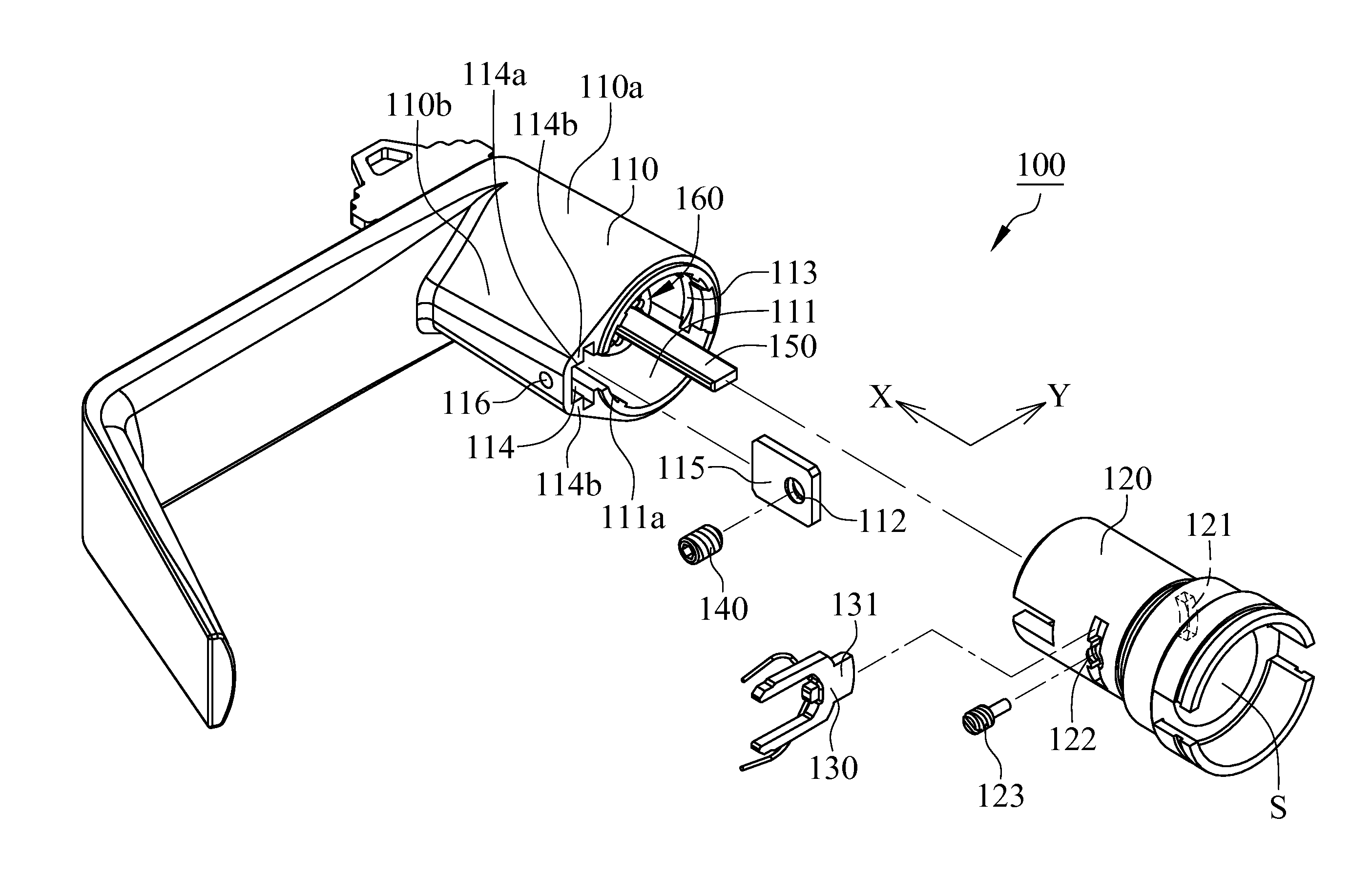
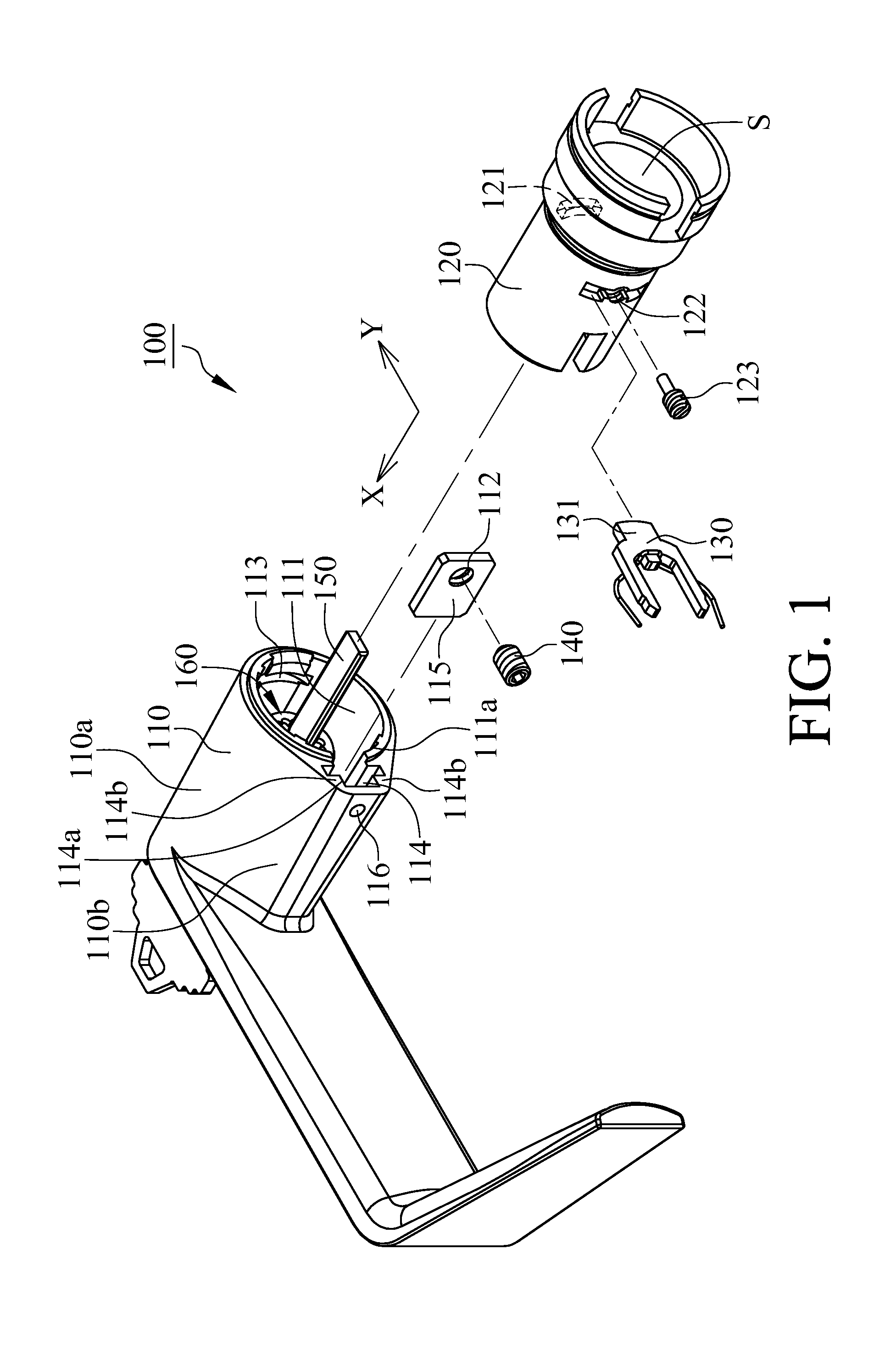
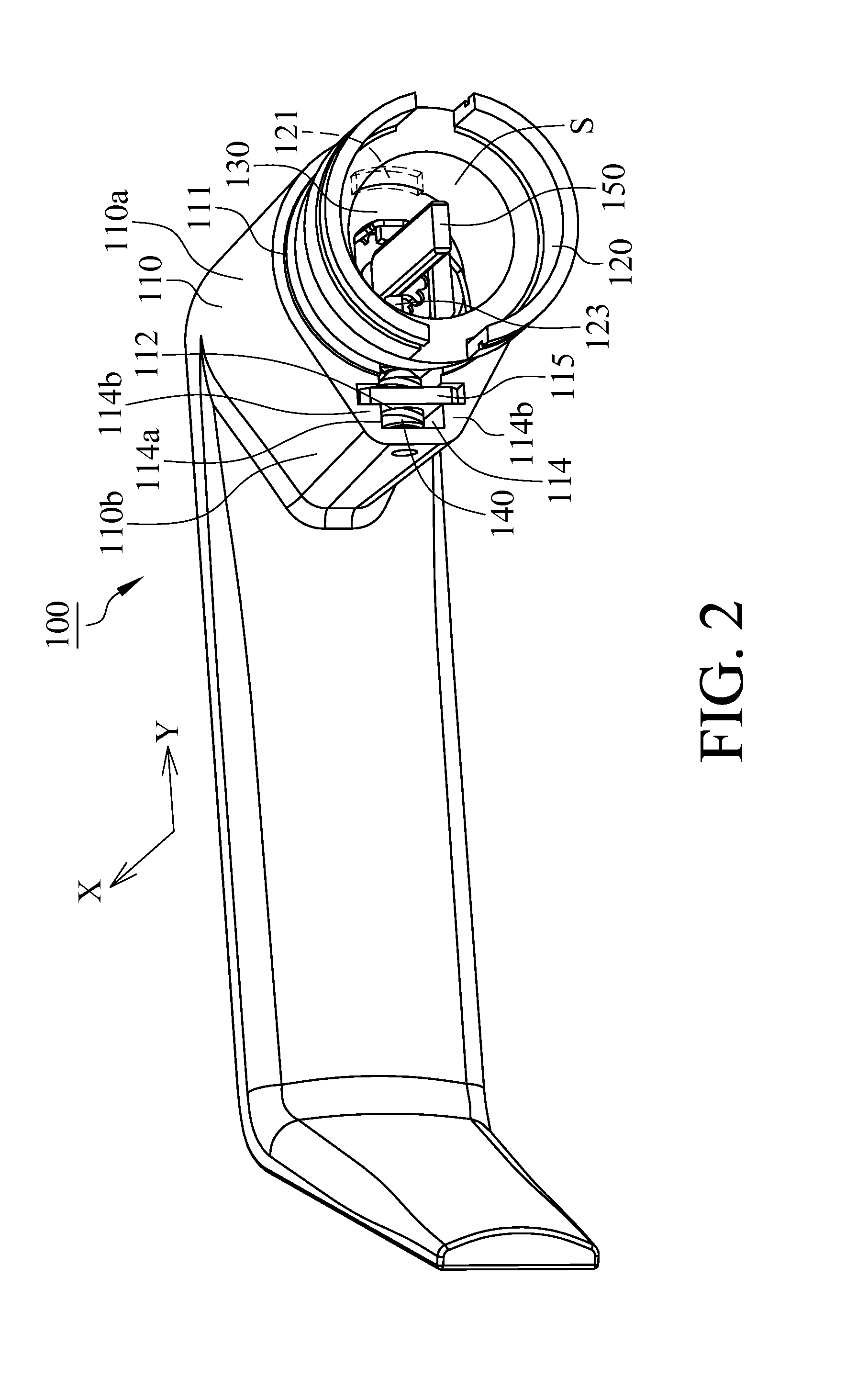
[0018]With reference to FIGS. 1 and 2, a handle assembly of a lock 100 in accordance with an embodiment of the present invention includes a handle 110, a sleeve 120, a stopper 130 and an engaging member 140, wherein the handle 110 comprises a body portion 110a, an accommodating slot 111 and a lodge hole 113. The accommodating slot 111 is defined by the body portion 110a, and the lodge hole 113 is formed at the body portion 110a. The sleeve 120 comprises a through hole 121 corresponded to the lodge hole 113 of the handle 110 and is disposed at the accommodating slot 111 along the direction of a major axis X. The stopper 130 comprises a lodge portion 131 and is disposed at the sleeve 120, wherein the lodge portion 131 penetrates through the through hole 121 of the sleeve 120, protrudes to the sleeve 120 and being lodged in the lodge hole 113 of the handle 110 for mutual engagement between the sleeve 120 and the handle 110.
[0019]With reference to FIGS. 1 and 2, the handle 110 further c...
PUM
 Abstract
Description
Claims
Application Information