
Handle assembly of lock

a technology of handle and handle, which is applied in the direction of mechanical equipment, anti-theft devices, transportation and packaging, etc., can solve the problem of not being able to separate the handle, and achieve the effects of avoiding swaying from the handle and the handle, enhancing the coupling strength between the handle and the sleeve, and effectively preventing the sleeve or the stopper

Active Publication Date: 2015-11-03
TAIWAN FU HSING INDAL
View PDF4 Cites 1 Cited by
  • Summary
  • Abstract
  • Description
  • Claims
  • Application Information

AI Technical Summary

Benefits of technology

The present invention aims to use an engaging member in a handle to prevent damage to the handle, sleeve, and stopper by avoiding sways during operation. The engaging member acts as a connection between the handle and sleeve, making them more stable and secure during use. This also ensures that the handle and sleeve are always stable and prevent any movement or sway during operation. Overall, the invention improves the connection between the handle and sleeve, reducing the likelihood of damage and improving the overall performance of the device.

Problems solved by technology

Therefore, colliding with the stopper and the transmission by an intruder can not separate the handle apart from the sleeve.

Method used


Image

  • Handle assembly of lock
  • Handle assembly of lock
  • Handle assembly of lock

Examples


Embodiment Construction

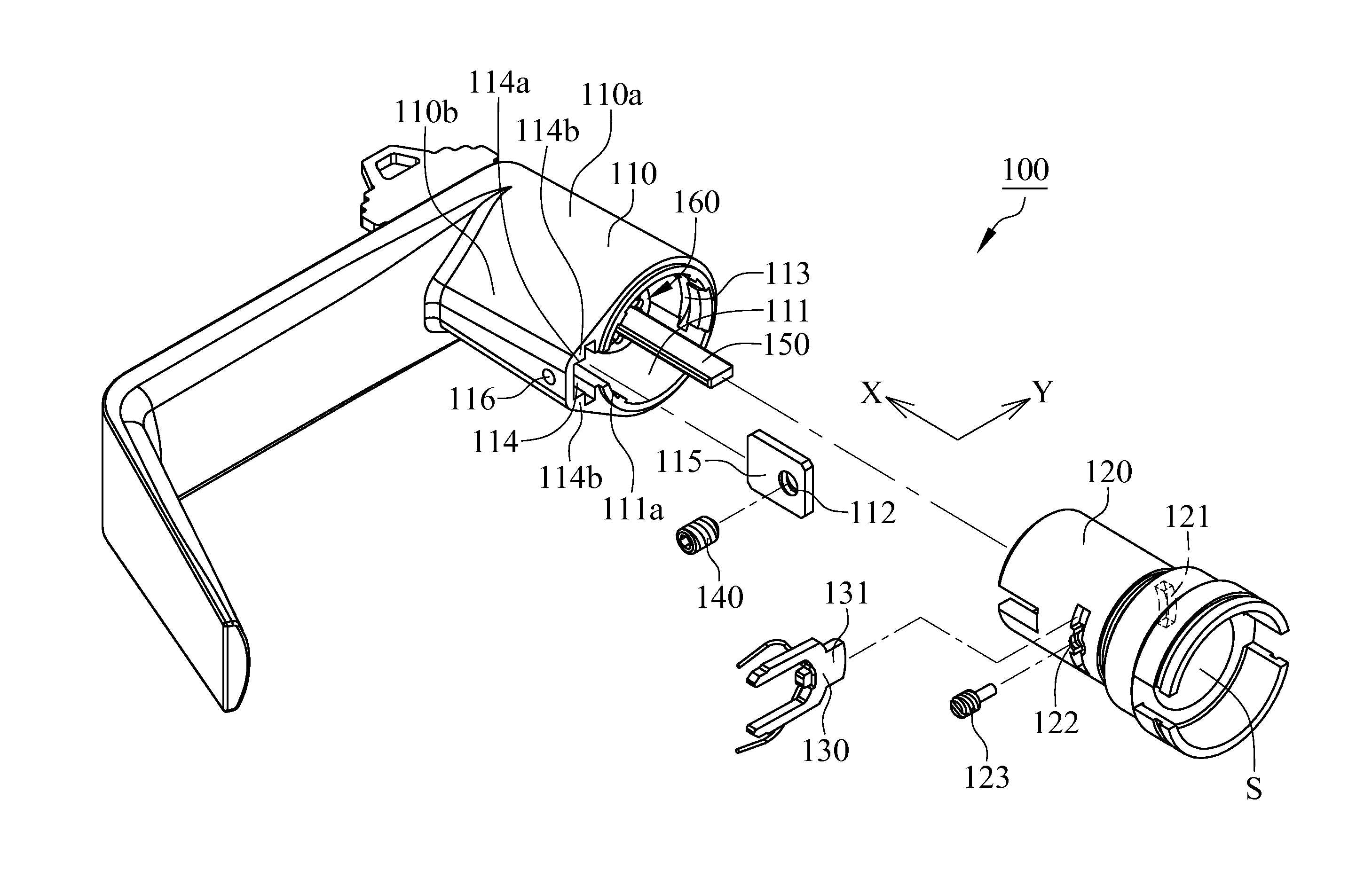
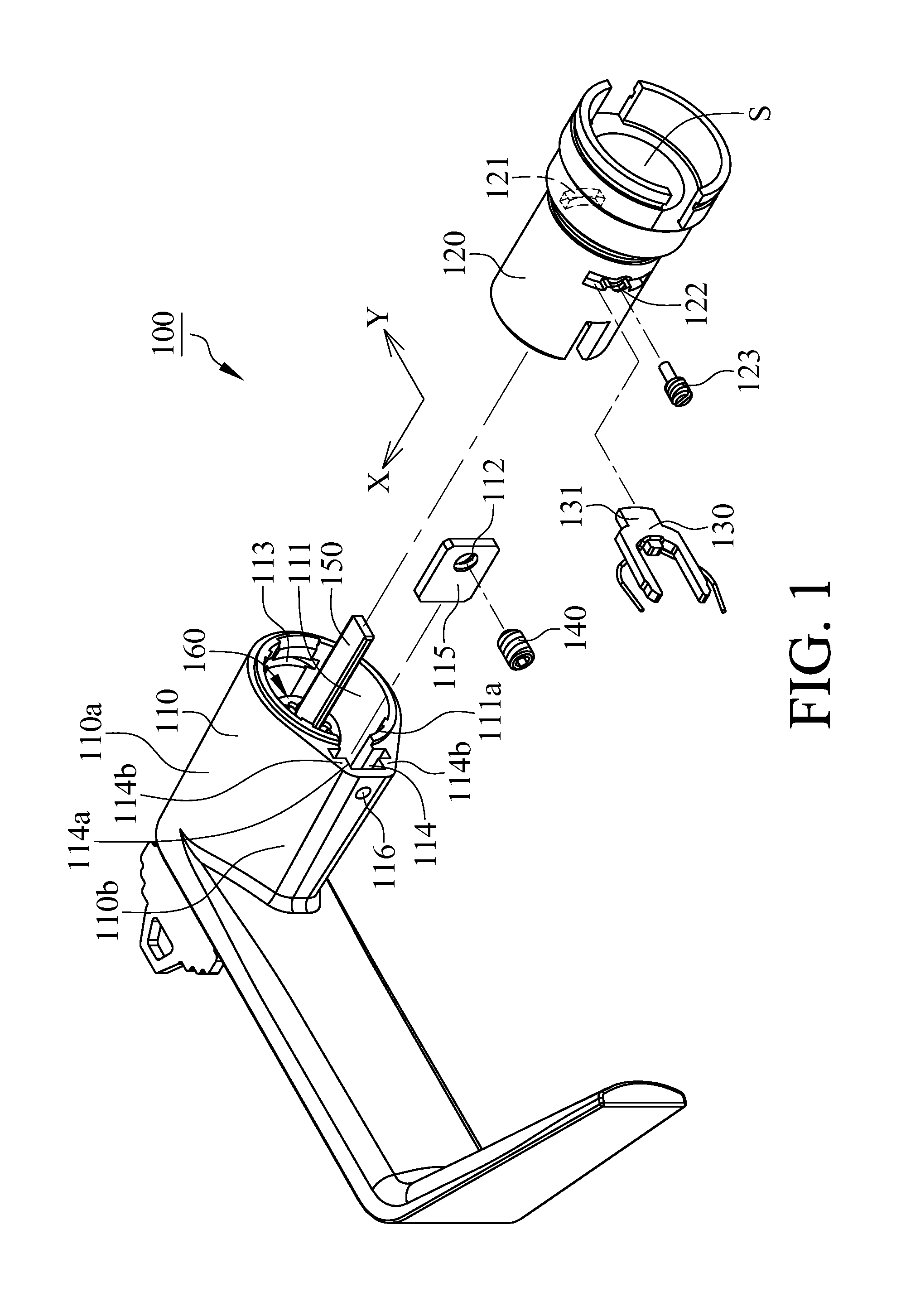
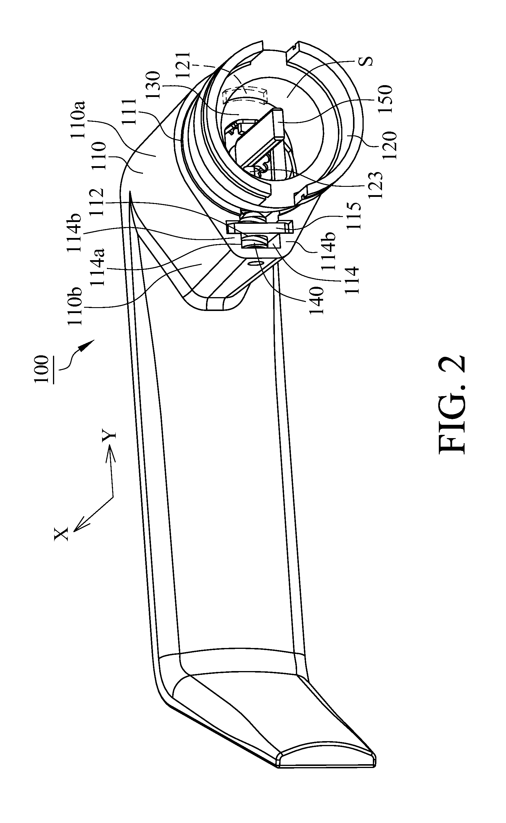
[0018]With reference to FIGS. 1 and 2, a handle assembly of a lock 100 in accordance with an embodiment of the present invention includes a handle 110, a sleeve 120, a stopper 130 and an engaging member 140, wherein the handle 110 comprises a body portion 110a, an accommodating slot 111 and a lodge hole 113. The accommodating slot 111 is defined by the body portion 110a, and the lodge hole 113 is formed at the body portion 110a. The sleeve 120 comprises a through hole 121 corresponded to the lodge hole 113 of the handle 110 and is disposed at the accommodating slot 111 along the direction of a major axis X. The stopper 130 comprises a lodge portion 131 and is disposed at the sleeve 120, wherein the lodge portion 131 penetrates through the through hole 121 of the sleeve 120, protrudes to the sleeve 120 and being lodged in the lodge hole 113 of the handle 110 for mutual engagement between the sleeve 120 and the handle 110.

[0019]With reference to FIGS. 1 and 2, the handle 110 further c...


PUM


Abstract

A handle assembly of a lock includes a handle, a sleeve, a stopper and an engaging member, wherein the handle comprises an accommodating slot, a lodge hole and a penetrating hole. The sleeve is disposed at the accommodating slot along the direction of a major axis and comprises a through hole. The stopper is disposed at the sleeve and protrudes to the sleeve via the through hole of the sleeve. Owing to the through hole corresponded to the lodge hole, the stopper is lodged in the lodge hole of the handle. The engaging member is disposed in the accommodating slot and adjustably movable along the direction of a transverse axis so that the handle and the sleeve are steadily engaged from each other.

Description

FIELD OF THE INVENTION[0001]The present invention is generally related to a handle assembly of a lock, which particularly relates to the handle assembly of the lock utilizing an engaging member to screw in an engaging hole of a handle to make the handle and a sleeve engaged from each other.BACKGROUND OF THE INVENTION[0002]With reference to FIG. 7, a conventional lock 200 includes a handle 210, a sleeve 220 and a stopper 230, wherein the handle 210 comprises an accommodating chamber 211, and the sleeve 220 is disposed within the accommodating chamber 211. There is an allowance between the sleeve 220 and the handle 210 to prevent the sleeve 220 from getting stuck inside the accommodating chamber 211. The stopper 230 is engaged with the handle 210 and the sleeve 220. When the handle 210 actuates the sleeve 220 to rotate via the stopper 230, the sleeve 220 and the handle 210 are severely swayed via the allowance between the sleeve 220 and the handle 210 therefore resulting in damage of ...

Claims


Application Information

Patent Timeline
Patent Type & Authority Patents(United States)
IPC IPC(8): B60R25/02E05B17/20E05B3/04E05B3/00E05B3/06
CPCE05B3/04E05B3/003E05B17/2084E05B3/00E05B3/06Y10T74/20732
Inventor HUANG, CHAO-MINGLEE, WEN-CHIEH
Owner TAIWAN FU HSING INDAL
Learn More