reactor

Active Publication Date: 2014-10-02
TAMURA KK
View PDF11 Cites 27 Cited by
  • Summary
  • Abstract
  • Description
  • Claims
  • Application Information

AI Technical Summary

Problems solved by technology

That is, it is difficult to directly connect a wiring like a covered electric wire to an end of the coil formed by letting a wire like a rectangular wire to be wound around such a coil.
When, however, molding is performed, depending on the shape of a mold to be utilized, and the position and shape of the core to be disposed inside the resin portion, the position and shape of the holder are restricted.
In addition, the shape of the mold becomes complex when merely molding the cylindrical bobbin with the resin-molded body in an integral manner.
Still further, the structure of the resin-molded body becomes complex when the core, the stay, and further the bus bar are embedded in the resin-molded body, making the manufacturing difficult.
When, however, the bus bar is embedded in the resin-molded body, the position of the bus bar is limited to the location where the bus bar is embedded in the resin-molded body only.
Therefore, it is difficult to draw the bus bar in optional directions, such as the front, rear, right and left of the reactor.
In particular, since the bus bar supplies power to the coil, it is necessary to ensure a sufficient insulation against the core and the stay, etc., but when the bus bar, the core, and the stay are present in the same resin-molded body, for the purpose of the insulation among those pieces, it is necessary to make the resin-molded body thickened, resul

Method used


Image

  • reactor
  • reactor
  • reactor

Examples


first embodiment

1. First Embodiment

[0045][Structure]

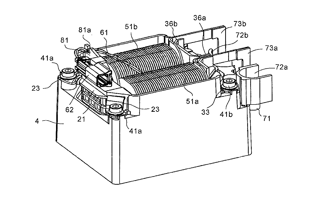
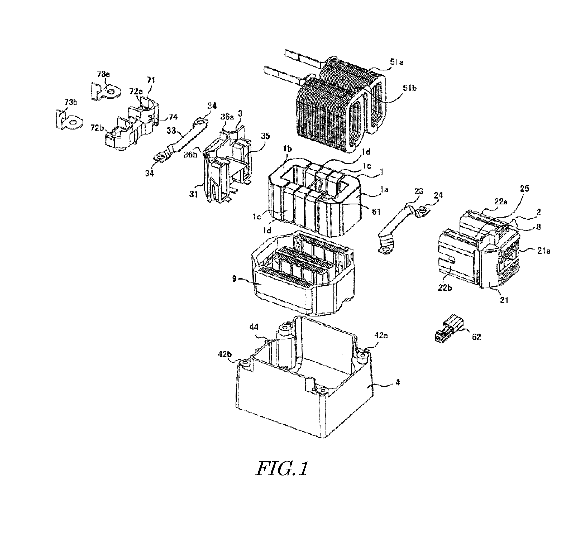
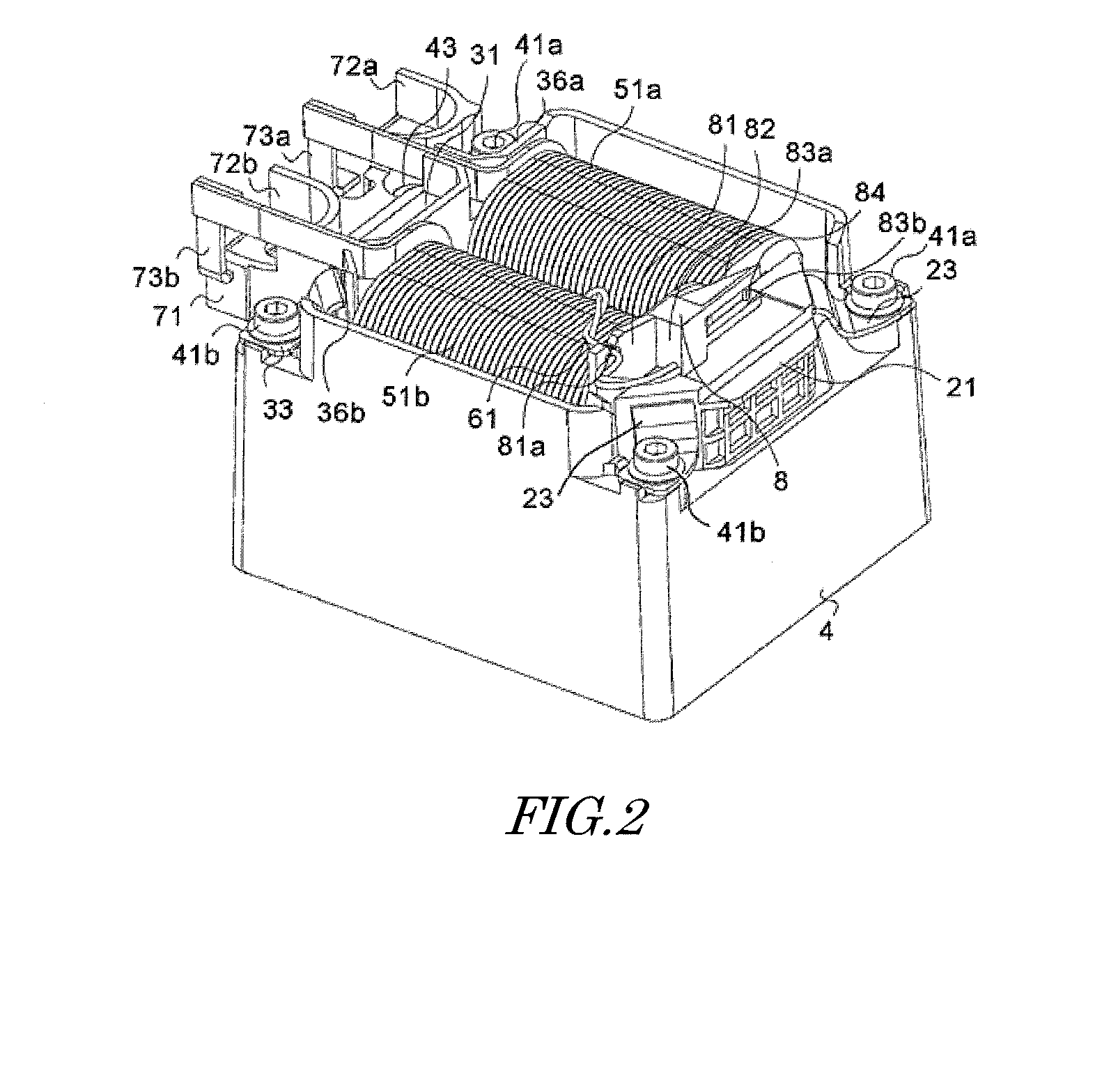
[0046]A reactor of this embodiment includes an annular core 1 which includes two U-shaped cores 1a, 1b forming a yoke of the reactor, and three I-shaped cores 1c forming each of right or left core leg. Those u-shaped cores 1a, 1b and the I-shaped cores 1c are connected via spacers 1d.

[0047]The annular core 1 is covered by two resin-molded bodies 2, 3 provided on the outer circumference of the annular core 1 at the bobbin side and at the terminal side. The resin-molded body 2 at the bobbin side includes right and left cylindrical bobbins 22a, 22b, and a core covering portion 21 provided so as to interconnect those. The first U-shaped core 1a is embedded in the interior of the covering portion 21 by molding. The three I-shaped cores 1c are inserted in the right or left bobbin 22a, 22b from the opening at the end of the bobbin. The resin-molded body 3 at the terminal side includes a core covering portion 31, and the second U-shaped core 1b is embedd...

second embodiment

2. Second Embodiment

[0057][Structure]

[0058]A reactor according to this embodiment includes the annular core 1 that has two U-shaped cores 1a, 1b which forms a yoke of the reactor and which are connected together via spacers 1d.

[0059]The annular core 1 is covered by a first resin-molded body 20 and a second resin-molded body 30 provided around the outer circumference of the annular core 1. The first resin-molded body 20 includes cylindrical right and left bobbins 22a, 22b, and a core covering portion 21 provided so as to interconnect those. A first U-shaped core 1a is embedded in the first resin-molded body 20 by molding. The second resin-molded body 30 includes right and left holders 32a, 32b, and a core covering portion 31, and a second U-shaped core 1b is embedded in the second resin-molded body 30 by molding.

[0060]Openings 21a, 31a utilized to hold the U-shaped cores 1a, 1b in a metal mold at the time of molding are provided in outer surfaces of the covering portions 21, 31, and...


PUM


Abstract

A reactor includes an annular core, coils, a sensor detecting a state of the reactor, and a connector outputting signal from the sensor. Resin-molded bodies are provided around the annular core. The resin-molded body has bobbins for the respective coils and core covering portions formed integrally with each other. An exposed area where no resin covers the bottom of the core is formed in the lower face of the covering portions. A holder to fasten the connector is formed integrally with the upper portion of the covering portion. An assembly including the resin-molded bodies in which the annular core is embedded, and the coils wound around the bobbins are retained in a metal casing. A clearance is formed between the assembly and the casing, and a filler is filled in this clearance. The filler covers the exposed area of the core bottom.

Description

CROSS-REFERENCE TO RELATED APPLICATIONS[0001]This application is based upon and claims the benefit of priority from Japanese Patent Application NO. 2013-074694, filed on Mar. 29, 2013 and Japanese Patent Application NO. 2013-242355, filed on Nov. 22, 2013; the entire contents all of which are incorporated herein by reference.FIELD OF THE INVENTION[0002]The present disclosure relates to a reactor having an improved disposition of a sensor connector.BACKGROUND ART[0003]Many reactors applied to an in-vehicle booster circuit employ a structure in which a coil is wound around a resin-made bobbin disposed around a core, those are retained in a metal casing, and a filler is filled in the casing and is let cured.[0004]Among those reactors, there is known a type which combines multiple divisional core pieces to form an annular core, and has coils wound around the right and left core legs. Each divisional core piece is embedded in a resin, and the resin portion serves as the covering portion ...

Claims


Application Information

Patent Timeline
IPC IPC(8): H01F27/00H01F27/40
CPCH01F27/402H01F27/008H01F27/00H01F27/263H01F27/29H01F27/306H01F27/325H01F37/00H01F2027/406
Inventor SUZUKI, KOTARONAKATSU, RYOINOUE, NAOKIMAENO, KENSUKE
Owner TAMURA KK
Why Eureka
Try Eureka