Laser radar device

a radar device and laser technology, applied in the direction of distance measurement, instruments, surveying and navigation, etc., can solve the problems of irregular reflection and possible reception of light projected to the dashboard

Active Publication Date: 2014-10-02
OMRON AUTOMOTIVE ELECTRONICS CO LTD
View PDF3 Cites 8 Cited by
  • Summary
  • Abstract
  • Description
  • Claims
  • Application Information

AI Technical Summary

Benefits of technology

[0028]Accordingly, the distance to the object presen

Problems solved by technology

In the case that the light shielding wall disclosed in Japanese Unexamined Patent Publication No. 2007-333592 is applied to the laser radar device placed inside the windshield, the light reflected from the windshield

Method used


Image

  • Laser radar device
  • Laser radar device
  • Laser radar device

Examples


Embodiment Construction

[0067]Embodiments of the present invention will be described with reference to the drawings. In embodiments of the invention, numerous specific details are set forth in order to provide a more thorough understanding of the invention. However, it will be apparent to one of ordinary skill in the art that the invention may be practiced without these specific details. In other instances, well-known features have not been described in detail to avoid obscuring the invention.

[0068][Configuration Example of Laser Radar Device]

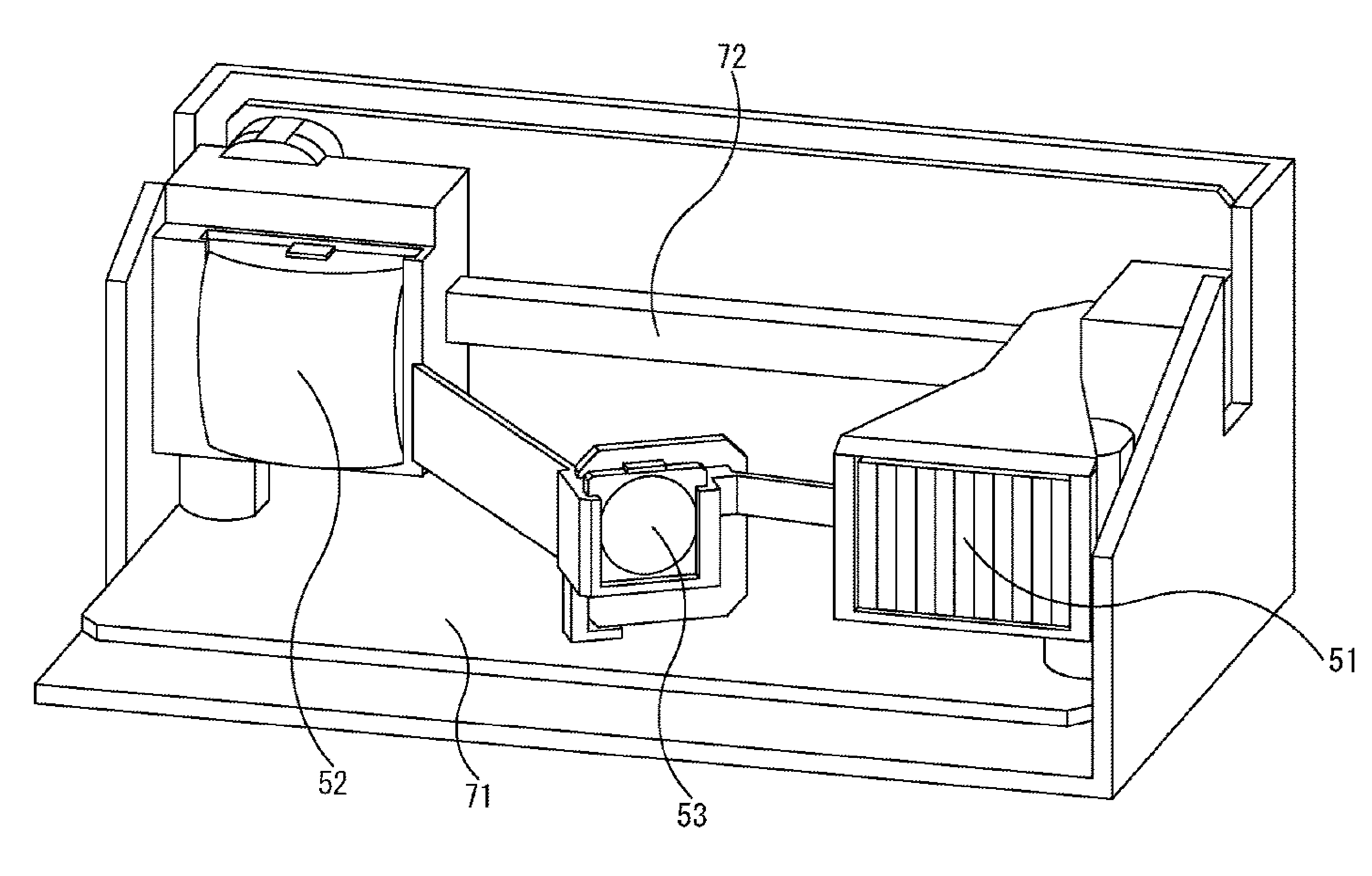
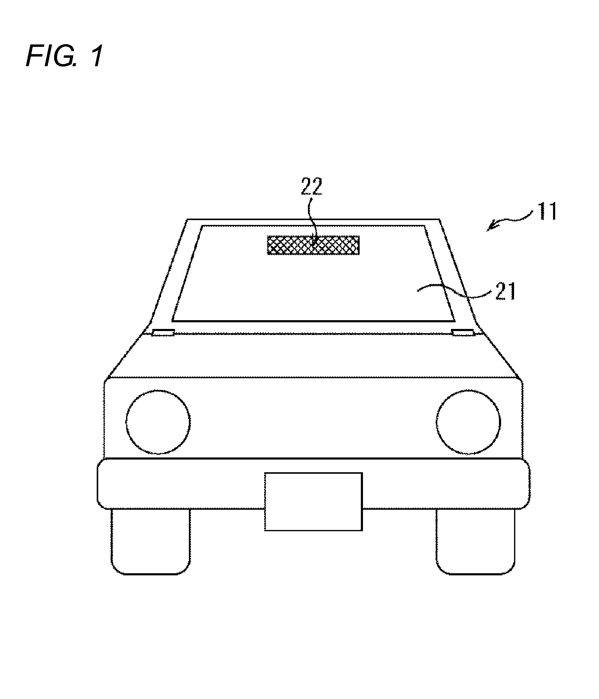
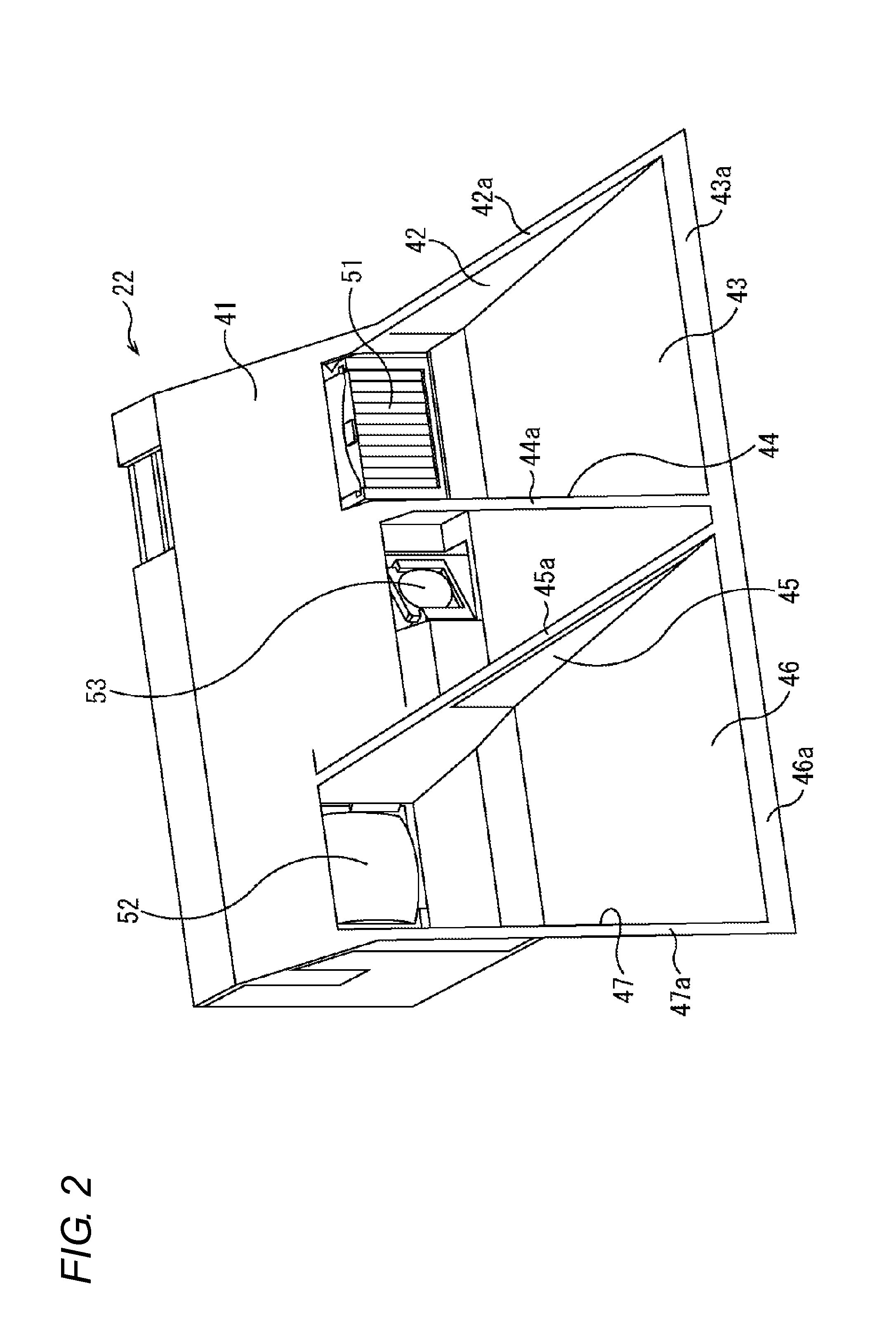
[0069]FIG. 1 is a view illustrating a configuration example of an appearance of a vehicle provided with a laser radar device according to one or more embodiments of the present invention. A vehicle 11 in FIG. 1 is provided with a laser radar device 22 that is located on an inside (vehicle interior) of a windshield 21 and a rear side of a rearview mirror (not illustrated). The laser radar device 22 projects light to a monitoring area ahead of the vehicle 11, and receiv...


PUM


Abstract

A laser radar device has a light projection part that projects light to a monitoring area outside a vehicle from a vehicle interior through a glass surface, a light receiving part that is placed a given distance away from the light projection part in a substantially horizontal direction to receive reflected light from an object outside the vehicle in the light projected by the light projection part through the glass surface, a measuring part that measures the distance to the object in the monitoring area based on timing when the light projection part projects the light and timing when the light receiving part receives the reflected light, and a light-projection shielding part that shields the light projected to an outside of the monitoring area in the light projected by the light projection part.

Description

BACKGROUND OF THE INVENTION[0001]1. Technical Field[0002]The present invention relates to a laser radar device, particularly to a laser radar device that can measure a distance to an object with high accuracy.[0003]2. Related Art[0004]A technology in which a radar device incorporated in a vehicle detects a vehicle in a traveling direction or a passing lane or a distance to an object to control vehicle motion according to the detected distance is becoming widespread.[0005]In a principle of the radar device, light is projected from a light projection part to a monitoring area, the light reflected from an object in the monitoring area is received, and a distance to the object is obtained from light projection timing and light receiving timing.[0006]Conventionally the in-vehicle radar device is frequently placed near a front end of a vehicle body. On the other hand, nowadays the in-vehicle radar device is occasionally placed inside a windshield (see Japanese Unexamined Patent Publicatio...

Claims


Application Information

Patent Timeline
IPC IPC(8): G01S17/88G01S17/931
CPCG01S17/88G01S7/481G01S17/931
Inventor ITAO, DAISUKEMIYAZAKI, HIDENORINISHIGUCHI, TADAOYASUGI, HIDEYUKIHIROTA, SATOSHI
Owner OMRON AUTOMOTIVE ELECTRONICS CO LTD
Why Eureka
Try Eureka