Mounting Clips For Panel Installation

a technology for installing clips and photovoltaic panels, which is applied in the direction of heat collector mounting/support, couplings, light and heating equipment, etc. it can solve the problems of high installation cost, difficult installation of mounting means commercially available, and high labor intensity for installing photovoltaic panels

Active Publication Date: 2014-10-02
GEORGIA TECH RES CORP
View PDF2 Cites 12 Cited by
  • Summary
  • Abstract
  • Description
  • Claims
  • Application Information

AI Technical Summary

Benefits of technology

[0009]In one aspect, a first mounting clip removably attaches one or more panels to a rail, both mechanically and electrically. The first mounting clip comprises a base having a leading edge and a trailing edge where the base is sized to fit on top of the rail. A plurality of locking clips is formed, extending upwardly away from the base towards the leading edge. Each of the plurality of locking clips provides upward force with regards to the base when pushed downwardly towards the base, acting like a spring. A central indexing tab is formed from the base uprightly and dividing the base in half lengthwise. The central indexing tab provides a z-direction guide for installing each of the one or more panels. At least two flanges are formed at each side of the base and angled downwardly away from the base. Each of the two flanges is configured to removably attach the base along each side of the rail. Further, a pair of lateral indexing tabs is formed uprightly along each side of the base where each of the pair of lateral indexing tabs is positioned and sized to receive one of the one or more panels in place. Each of the pair of lateral indexing tab further comprises a sliding slot defined between each of the pair of lateral indexing tab and the base having an opening end at the trailing edge. A vertical indexing tab is formed at each end of the pair of lateral indexing tabs, extending outwardly with respect to each of the lateral indexing tab at a perpendicular angle while the vertical indexing tab provides an x-direction guide for installing each of the one or more panels.
[0010]In another aspect, second mounting clip comprises a base where a plurality of spring bonding tabs is formed. Each of the plurality of spring bonding tabs extends at an angle upwardly away from the base and rises towards the trailing edge. A top flange is formed above and parallel to the base at the trailing edge where the top flange prevents movement of or more panels in y-direction. A side flange is formed side of the base and angled downwardly away from the central indexing tab is formed from the base uprightly, dividing the base in half lengthwise. The central indexing tab provides a z-direction guide for installing the panels. Finally, a vertical indexing tab is formed at each side of the base at the leading edge. The vertical indexing tab provides a z-direction guide for installing each of the one or more panels in conjunction with the central indexing tab.

Problems solved by technology

However, they are an expensive solution, not only because of the cost of the photovoltaic panels themselves, but also because of the cost of installation of the photovoltaic panels.
Typically, installation of photovoltaic panels requires highly trained installers and many hours of labor to properly align the panels and install them securely and accurately.
The mounting means commercially available are difficult to install and require many different parts and tools to assemble the photovoltaic array.
In addition, mounting means usually do not provide both mechanical fastening and electrical bonding of the photovoltaic panel.

Method used


Image

  • Mounting Clips For Panel Installation
  • Mounting Clips For Panel Installation
  • Mounting Clips For Panel Installation

Examples


Embodiment Construction

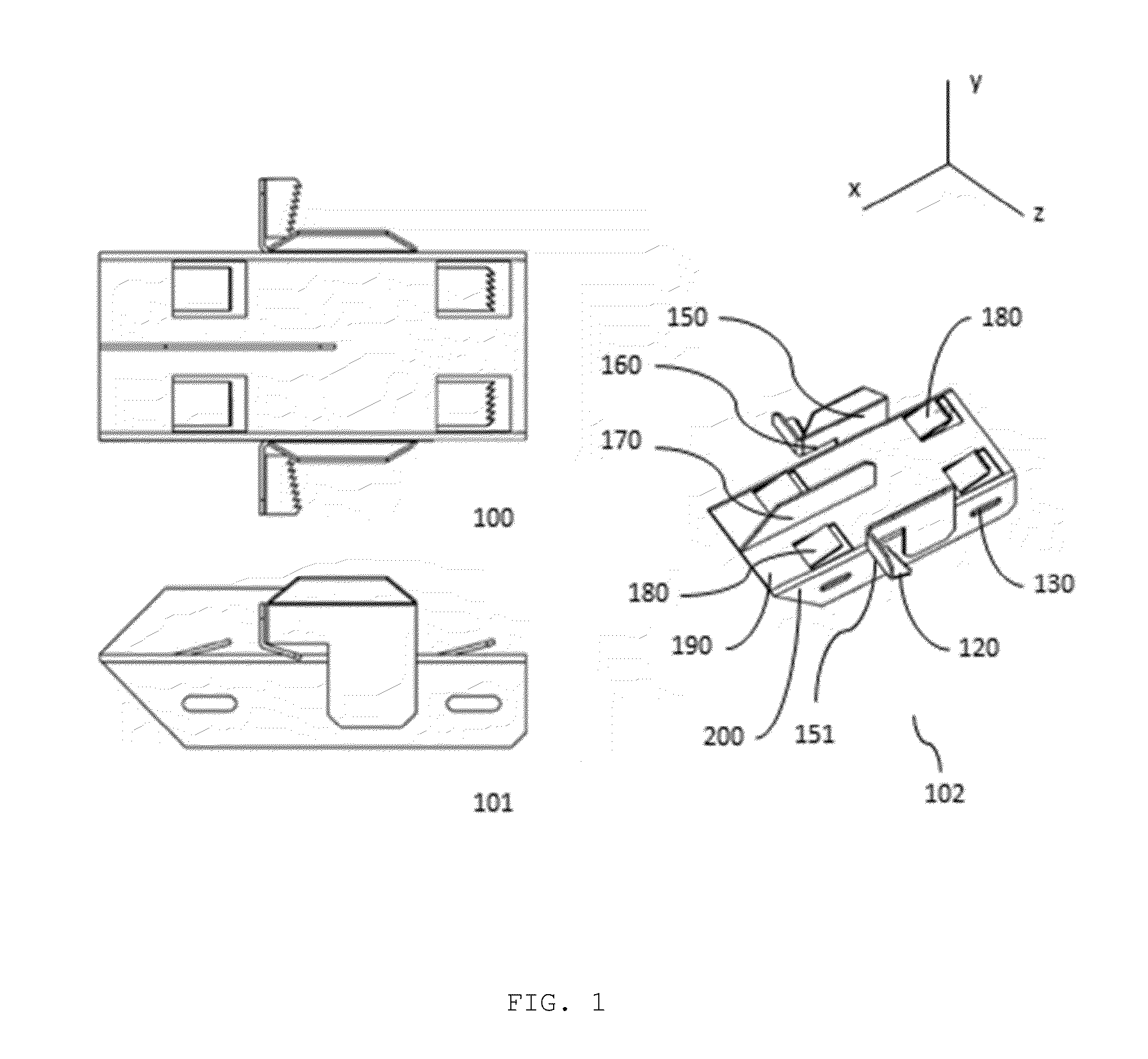
[0026]The detailed description set forth below in connection with the appended drawings is intended as a description of presently preferred embodiments of the invention and does not represent the only forms in which the present invention may be constructed and / or utilized. The description sets forth the functions and the sequence of steps for constructing and operating the invention in connection with the illustrated embodiments.

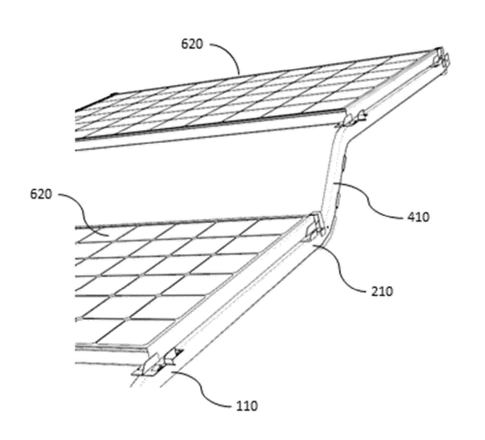
[0027]Photovoltaic panels are commonly installed suspending away from an installation surface. Generally, a structure is placed under the photovoltaic panels providing a mounting surface. It requires an accurate measurement in order to mount the photovoltaic panels at the right mounting points, which relates to increase in time and cost of installation. Currently, photovoltaic panel mounting means have several shortcomings, such as, lack of electrical bonding of the photovoltaic panels to the mounting surface and highly complex installation process due to la...


PUM


Abstract

A photovoltaic panel mounting clip is disclosed. The mounting clip bonds the panel to a beam or the like structure, both mechanically and electrically. It provides secure locking of the panel in all directions, while providing guidance in all direction for accurate installation of the panel to a mounting structure. The disclosed invention enables easy installation of the panels without excessive use of time, tools, or cost.

Description

CROSS-REFERENCE TO RELATED APPLICATIONS[0001]This application is a non-provisional application which claims the benefit to Provisional Application No. 61 / 807,416 filed on Apr. 2, 2013 and Provisional Application No. 61 / 806,203 filed on Mar. 28, 2013.BACKGROUND[0002]1. Field of the Invention[0003]The present invention relates generally to mounting means for photovoltaic panel installation systems. More particularly, the present invention relates to mounting clips for photovoltaic panel installation on a mounting structure that provides easy installation and electrical bonding.[0004]2. Description of Related Art[0005]Photovoltaic panels are an environmentally friendly solution to generating electricity. However, they are an expensive solution, not only because of the cost of the photovoltaic panels themselves, but also because of the cost of installation of the photovoltaic panels. Typically, installation of photovoltaic panels requires highly trained installers and many hours of labo...

Claims


Application Information

Patent Timeline
Patent Type & Authority Applications(United States)
IPC IPC(8): F16B2/24
CPCF16B2/241F16B5/125F24S25/11F24S25/13F24S25/632F24S2025/02Y02E10/47Y02E10/50Y10T403/602F16B5/0685H02S30/10
Inventor CAVIERES, ANDRESAL-HADDAD, TRISTANGOODMAN, JOSEPH
Owner GEORGIA TECH RES CORP
Why Eureka
Try Eureka