Method and apparatus for lifting an integrated circuit from a socket

a technology of integrated circuits and sockets, applied in the field of sockets, can solve the problems of causing pin damage and giving the user very little to grasp

Inactive Publication Date: 2002-08-27
ADVANCED MICRO DEVICES INC
View PDF6 Cites 7 Cited by
  • Summary
  • Abstract
  • Description
  • Claims
  • Application Information

AI Technical Summary

Benefits of technology

In an embodiment, the lift mechanism moves at least partially vertically downward in response to the cover moving in a second lateral direction (towards a closed position), to thereby prevent the lift mechanism from hindering insertion of the integrated circuit in the socket.
In an embodiment, the base portion includes a ramp, with which the lift mechanism engages when the cover is moved laterally in the first direction. Engagement with the ramp forces the lift mechanism at least partially upward so as to upwardly displace an integrated circuit inserted in the socket. The lift mechanism disengages with the ramp when the cover is moved laterally towards a closed position sufficiently to allow the lift mechanism to move at least partially in a downward vertical direction, to thereby prevent the lift mechanism from hindering insertion of the integrated circuit in the socket.
In another embodiment an electrical socket includes a base and a cover that slidably engages with the base portion. The socket includes an actuation device that moves the cover laterally with respect to the base. A spring extends from the base portion and a projection, preferably integral with the cover, engages the spring as the cover is moved laterally into a closed position to thereby prevent the spring from exerting a vertical biasing force on an integrated circuit inserted in the socket. The projection disengages from the spring when the cover is moved laterally into an open position to allow the spring to exert an upward force on an integrated circuit inserted in the socket, thereby allowing a user to grasp the integrated circuit for removal.

Problems solved by technology

Such packages tend to give the user very little to grasp when trying to remove the package from the socket.
In addition some users resort to metal tools to lift one side of the package first, which also risks damage to the pins.

Method used


Image

  • Method and apparatus for lifting an integrated circuit from a socket
  • Method and apparatus for lifting an integrated circuit from a socket
  • Method and apparatus for lifting an integrated circuit from a socket

Examples


Embodiment Construction

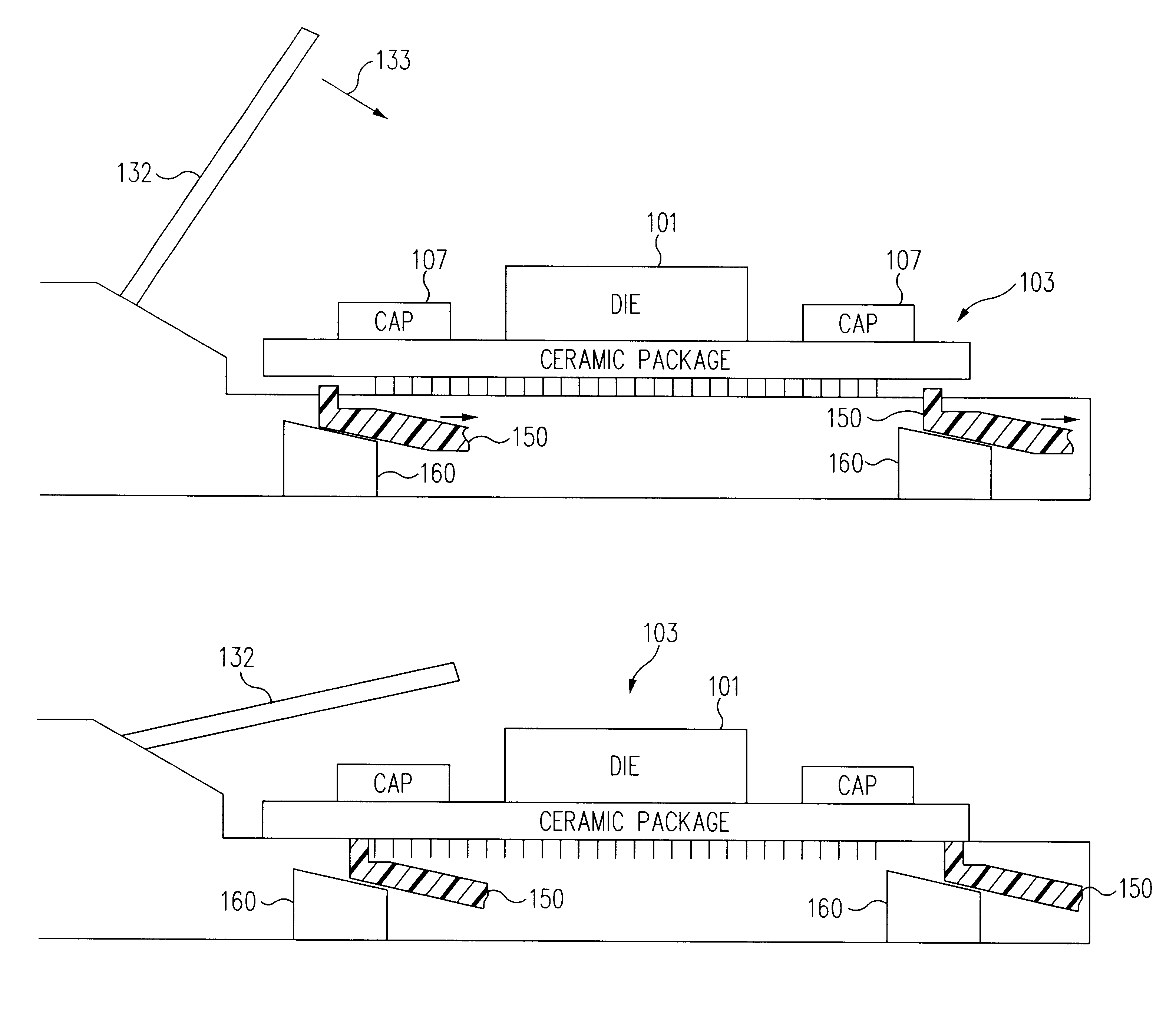
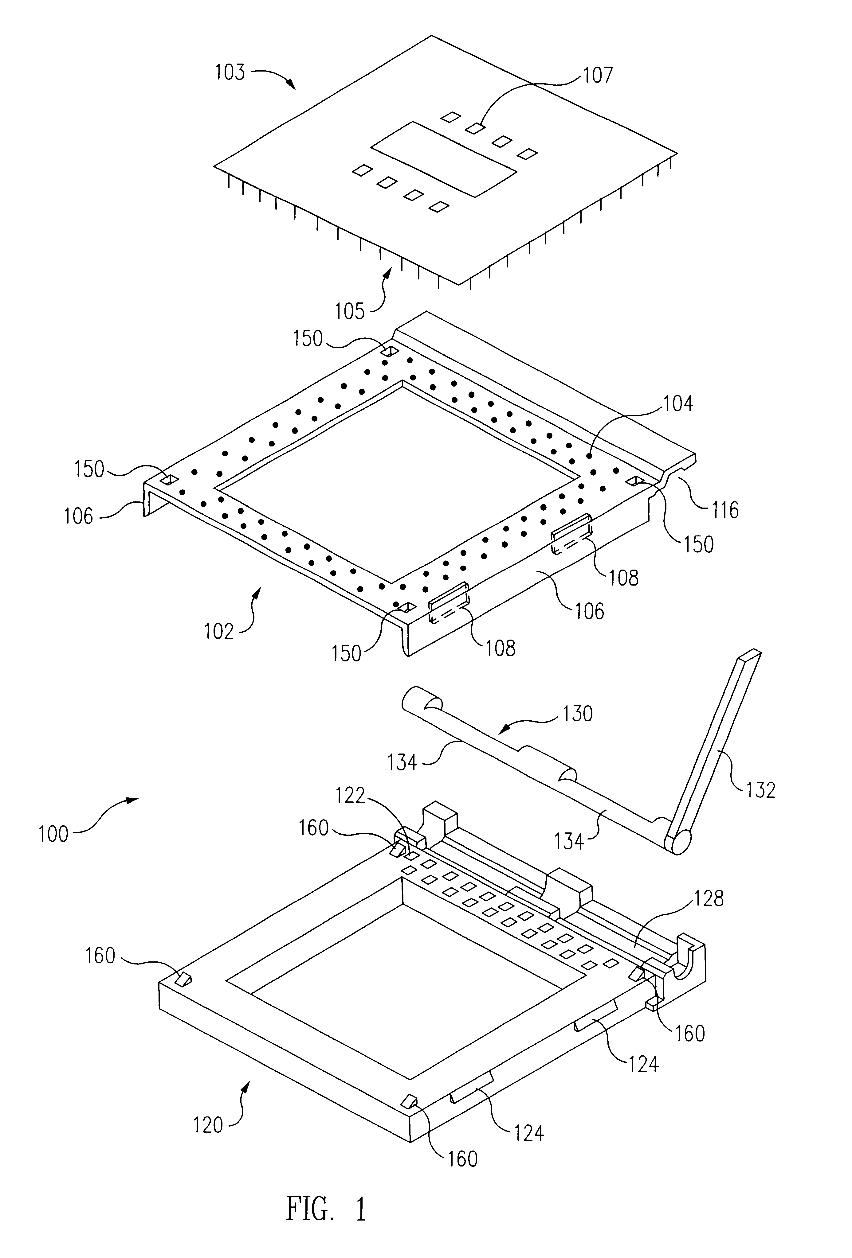
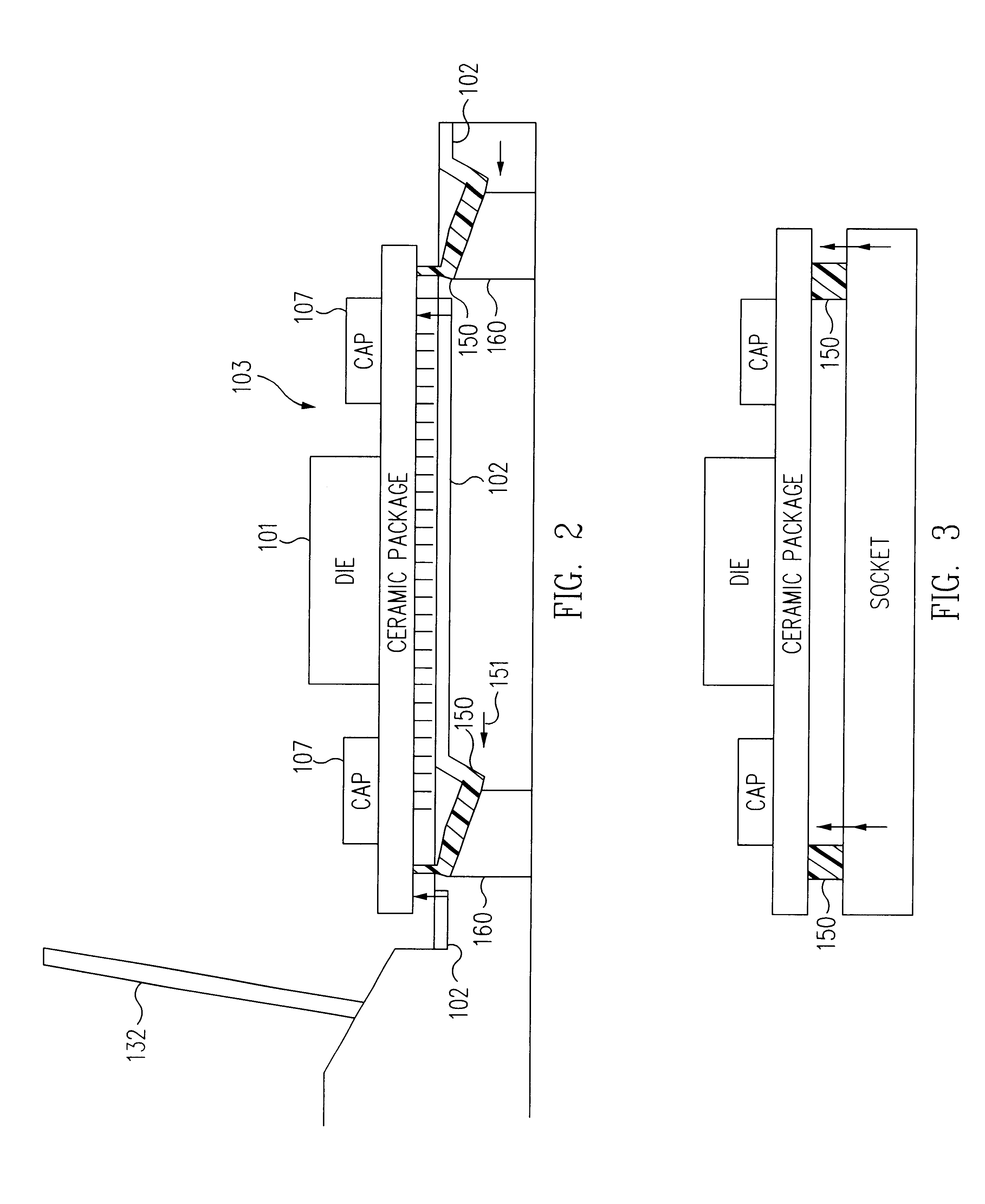
A zero insertion force (ZIF) pin grid array (PGA) socket 100 and an integrated circuit 103 in a PGA package for use with the ZIF socket 100 are shown in FIG. 1. The ZIF socket 100 includes a cover 102 that has a plurality of passageways 104 therethrough. The cover 102 is slidably attached to a base 120. The base 120 includes a plurality of slots 122, which are aligned with corresponding first passageways 104. Note that the slots only on one side of base 120 are illustrated on FIG. 1. Each slot 122 includes a contact for electrical and mechanical engagement with a pin 105 of an integrated circuit 103 when the integrated circuit 103 is inserted in the socket.

The cover 102 comprises two side walls 106 extending downward from the top of the cover 102. Each side wall 106 includes openings 108 (only two openings in the near side wall shown). The base 120 forms two protrusions 124 on each of its side walls which are received by the corresponding openings 108 of each side wall 106 of the co...


PUM


Abstract

A lift mechanism is provided that facilitates removal of an integrated circuit from a socket. Such a socket includes a base portion and a cover that slidably engages with the base portion. An actuation device moves the cover laterally with respect to the base. A lift mechanism responds to the cover moving in a first lateral direction into an open position in which the integrated circuit can be removed from the socket, by moving at least partially in an upward direction sufficiently to displace the integrated circuit away from the socket, thereby more easily allowing the integrated circuit to be grasped and removed from the socket.

Description

1. Field of the InventionThis invention relates to sockets utilized in conjunction with integrated circuits and more particularly to facilitating the removal of a packaged integrated circuit from a socket.2. Description of the Related ArtPrior art packaging techniques include packaging integrated circuits such as central processing units (CPUs) in ceramic pin grid array (PGA) packages. Such packaged CPUs were often placed in zero insertion force (ZIF) sockets on, e.g., motherboards of computer systems. ZIF sockets allow an integrated circuit in a PGA package to be placed into the socket without causing any force to be exerted on the pins of the packaged integrated circuit. Then a handle or other tool is used to cause mechanical and electrical connections to engage the pins. To remove the integrated circuit, the tool is used to mechanically and electrically disengage the pins of the PGA package from the socket, and then the integrated circuit can be removed from the ZIF socket. In th...

Claims


Application Information

Patent Timeline
Patent Type & Authority Patents(United States)
IPC IPC(8): H01R13/633
CPCH01R13/6335
Inventor ANDRIC, ANTHONYHILL, RUELMARKWARDT, DOUG
Owner ADVANCED MICRO DEVICES INC
Why Eureka
Try Eureka