Monitoring Flow Rates While Retrieving Bottom Hole Assembly During Casing While Drilling Operations

a technology of flow rate and casing, which is applied in the direction of drilling pipes, surveying, borehole/well accessories, etc., can solve the problems of increasing the hydrostatic pressure of the fluid in the annulus, and the operator may temporarily cease to flow fluid down the annulus

Inactive Publication Date: 2009-11-26
SCHLUMBERGER TECH CORP
View PDF6 Cites 19 Cited by
  • Summary
  • Abstract
  • Description
  • Claims
  • Application Information

AI Technical Summary

Benefits of technology

[0006]In the preferred embodiment, the operator reduces the density of the fluid in the casing string above the bottom hole assembly to less than the fluid in the annulus, creating an upward force on the bottom hole assembly. If desired, a wireline may be attached to the bottom hole assembly. Pulling upward on the wireline will assist in upward movement of the bottom hole assembly. Preferably, the displaced fluid flows through a restrictive orifice to create a desired back pressure. The flow area may be varied as the bottom hole assembly moves upward.

Problems solved by technology

If the flow rates differ too much, the operator may temporarily cease to flow fluid down the annulus.
Alternately, it could result in an increase in hydrostatic pressure of the fluid in the annulus.

Method used


Image

  • Monitoring Flow Rates While Retrieving Bottom Hole Assembly During Casing While Drilling Operations
  • Monitoring Flow Rates While Retrieving Bottom Hole Assembly During Casing While Drilling Operations
  • Monitoring Flow Rates While Retrieving Bottom Hole Assembly During Casing While Drilling Operations

Examples


Embodiment Construction

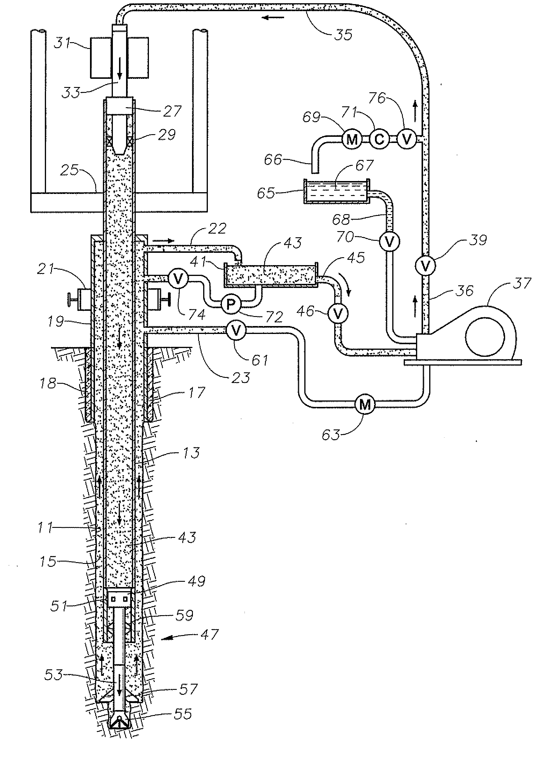
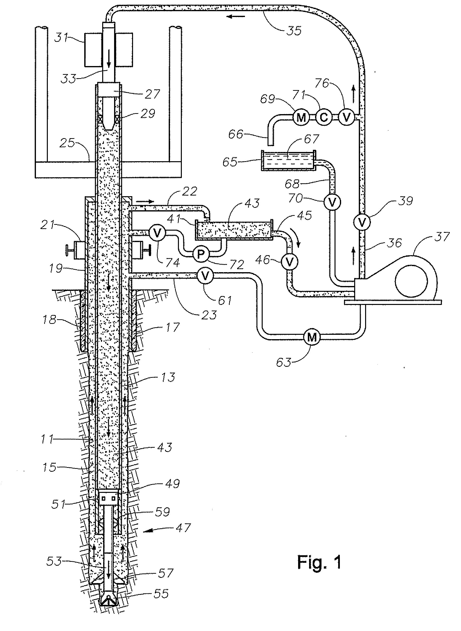
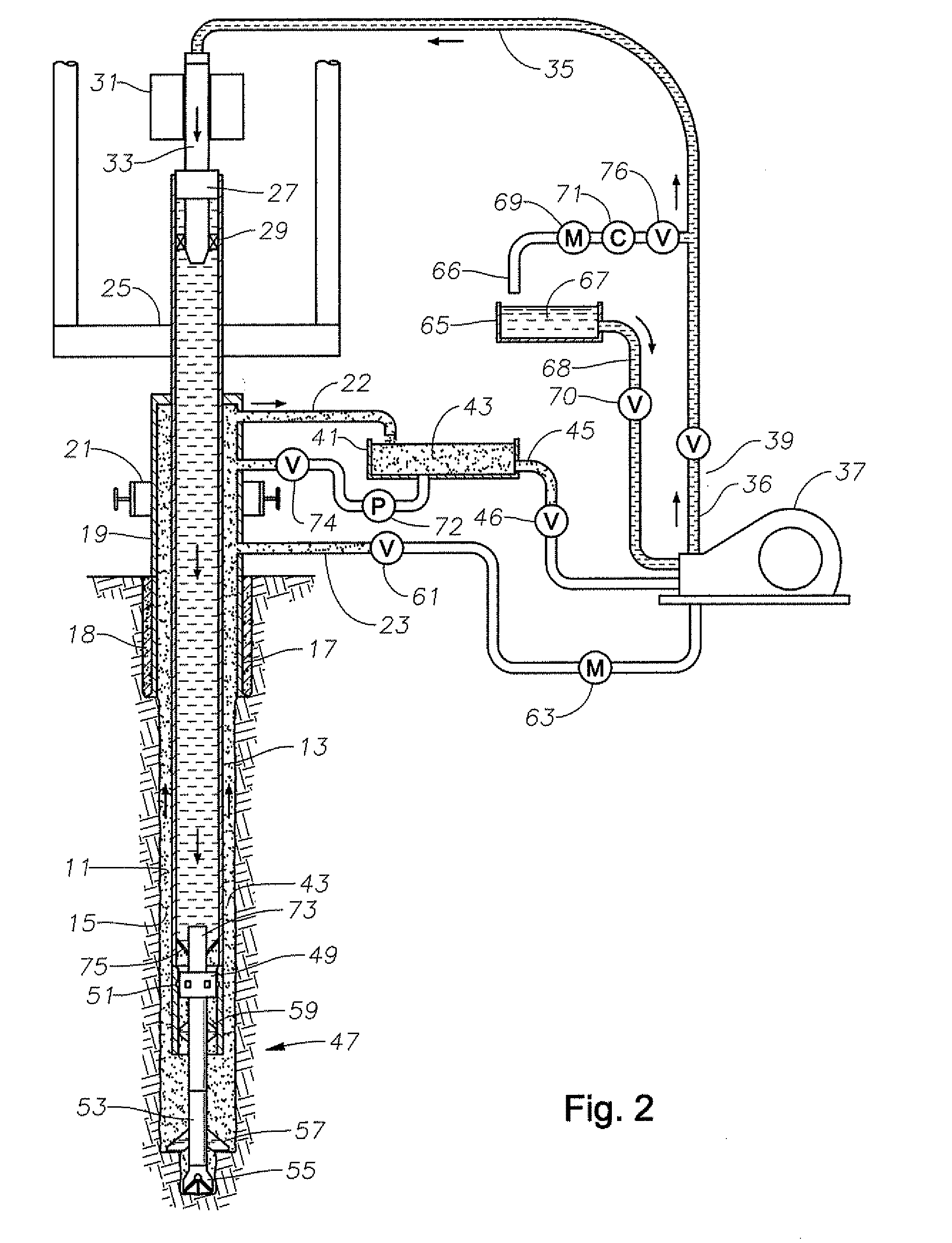
[0021]Referring to FIG. 1, a borehole 11 is shown being drilled. A casing string 13 is lowered into borehole 11. An annulus 15 is located between the sidewall of borehole 11 and casing string 13. One or more strings of casing 17 have already been installed and cemented in place by cement 18, although the drawings shows only one casing string for convenience, Annulus 15 thus extends from the bottom of casing string 13 up the annular space between casing string 13 and casing 17.

[0022]A wellhead assembly 19 is located at the surface. Wellhead assembly 19 will differ from one drilling rig to another, but preferably has a blowout preventer 21 (BOP) that is capable of closing and sealing around casing 17. An annulus outlet flowline 22 extends from wellhead assembly 19 at a point above BOP 21. An annulus inlet flowline 23 extends from wellhead assembly 19 from a point below BOP 21.

[0023]Casing string 13 extends upward through an opening in rig floor 25 that will have a set of slips (not sh...


PUM


Abstract

A bottom hole assembly in a casing-while-drilling operation is retrieved by reducing the density of the fluid in the casing string above the bottom hole assembly, creating an upward force on the bottom hole assembly. As the bottom hole assembly moves upward in the casing string, fluid is pumped into the upper end of the annulus and displaced fluid flows out of the upper end of the casing string. The flow rate of the fluid flowing into the upper end of the annulus and the flow rate of the displaced fluid flowing out of the casing string are monitored and compared.

Description

BACKGROUND OF THE INVENTION[0001]Casing-while-drilling is a technique that involves running the casing at the same time the well is being drilled. The operator locks a bottom hole assembly to the lower end of the casing. The bottom hole assembly has a pilot drill bit and a reamer for drilling the borehole as the casing is lowered into the earth. The operator pumps drilling mud down the casing string, which returns up the annulus surrounding the casing string along with cuttings. The operator may rotate the casing with the bottom hole assembly. Alternatively, the operator may employ a mud motor that is powered by the downward flowing drilling fluid and which rotates the drill bit.[0002]When the total depth has been reached, unless the drill bit is to be cemented in the well, the operator will want to retrieve it through the casing string and install a cement valve for cementing the casing string. Also, at times, it may be necessary to retrieve the bottom hole assembly through the cas...

Claims


Application Information

Patent Timeline
Patent Type & Authority Applications(United States)
IPC IPC(8): E21B23/14
CPCE21B7/20E21B7/208E21B19/084E21B2021/006E21B21/10E21B21/106E21B23/08E21B21/06E21B21/085
Inventor ERIKSEN, ERIK P.MOFFITT, MICHAEL E.WARREN, TOMMY M.
Owner SCHLUMBERGER TECH CORP
Why Eureka
Try Eureka