Brushless motor

a brushless motor and motor body technology, applied in the direction of dynamo-electric machines, electrical equipment, magnetic circuit shapes/forms/construction, etc., can solve the problem that the end surfaces of the back yokes of the pole pieces do not appropriately come into contact with each other, and achieve the effect of preventing the degradation of the dimension accuracy of the stator

Inactive Publication Date: 2014-10-09
AISAN IND CO LTD
View PDF5 Cites 13 Cited by
  • Summary
  • Abstract
  • Description
  • Claims
  • Application Information

AI Technical Summary

Benefits of technology

[0009]With this configuration, when a dimension of the core body in the opened state varies among the stators, variation is offset by narrowing and widening the gap between at least one pair of the facing surfaces. As a result, the degradation of the dimension accuracy of the stator may be prevented.

Problems solved by technology

In an above-described technique, when a length of the laminated core having the pole pieces linearly arranged varies among products, the end surfaces of the back yokes of the pole pieces do not appropriately come into contact with each other.

Method used


Image

  • Brushless motor
  • Brushless motor
  • Brushless motor

Examples


first embodiment

Modification of First Embodiment

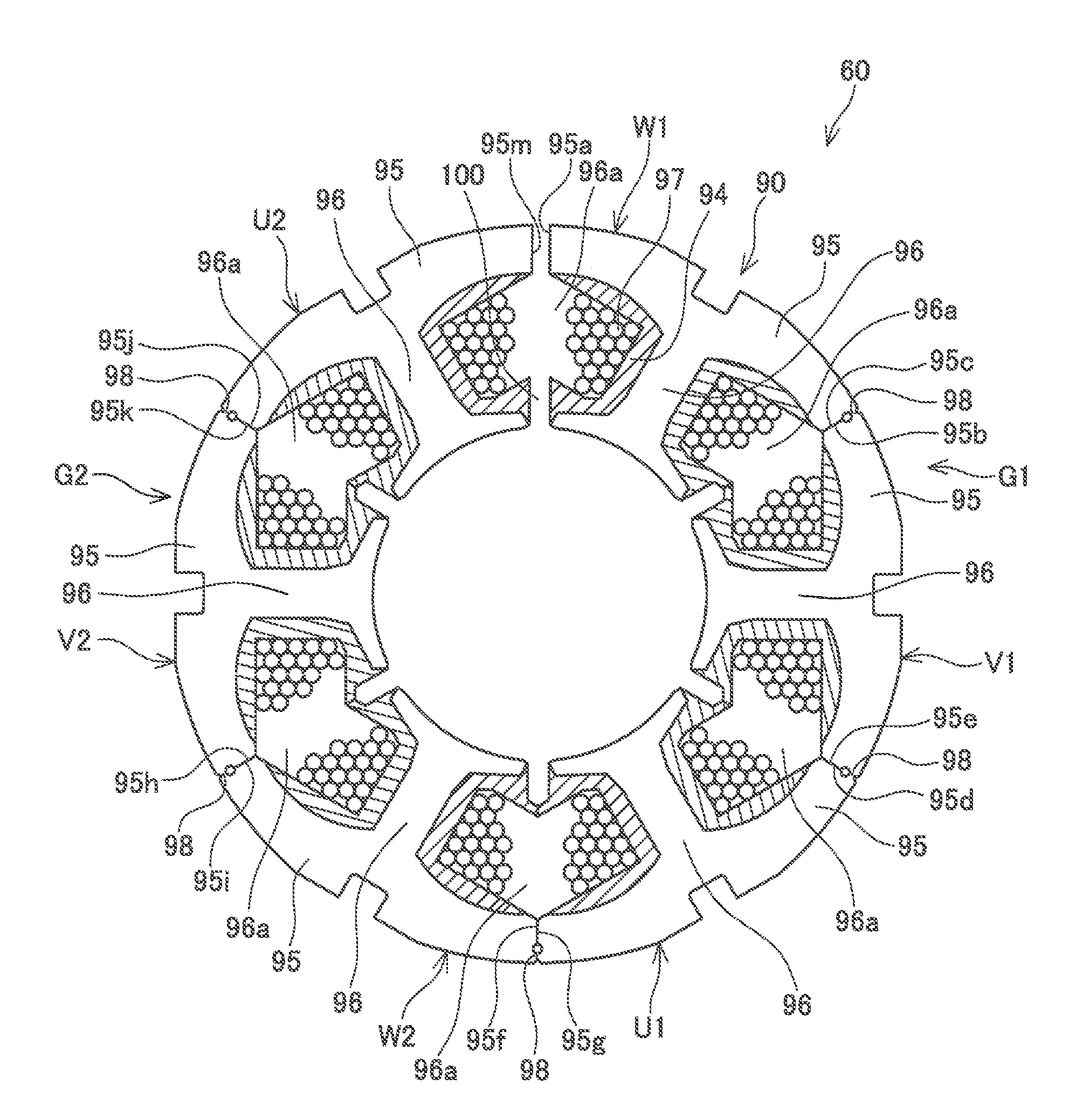
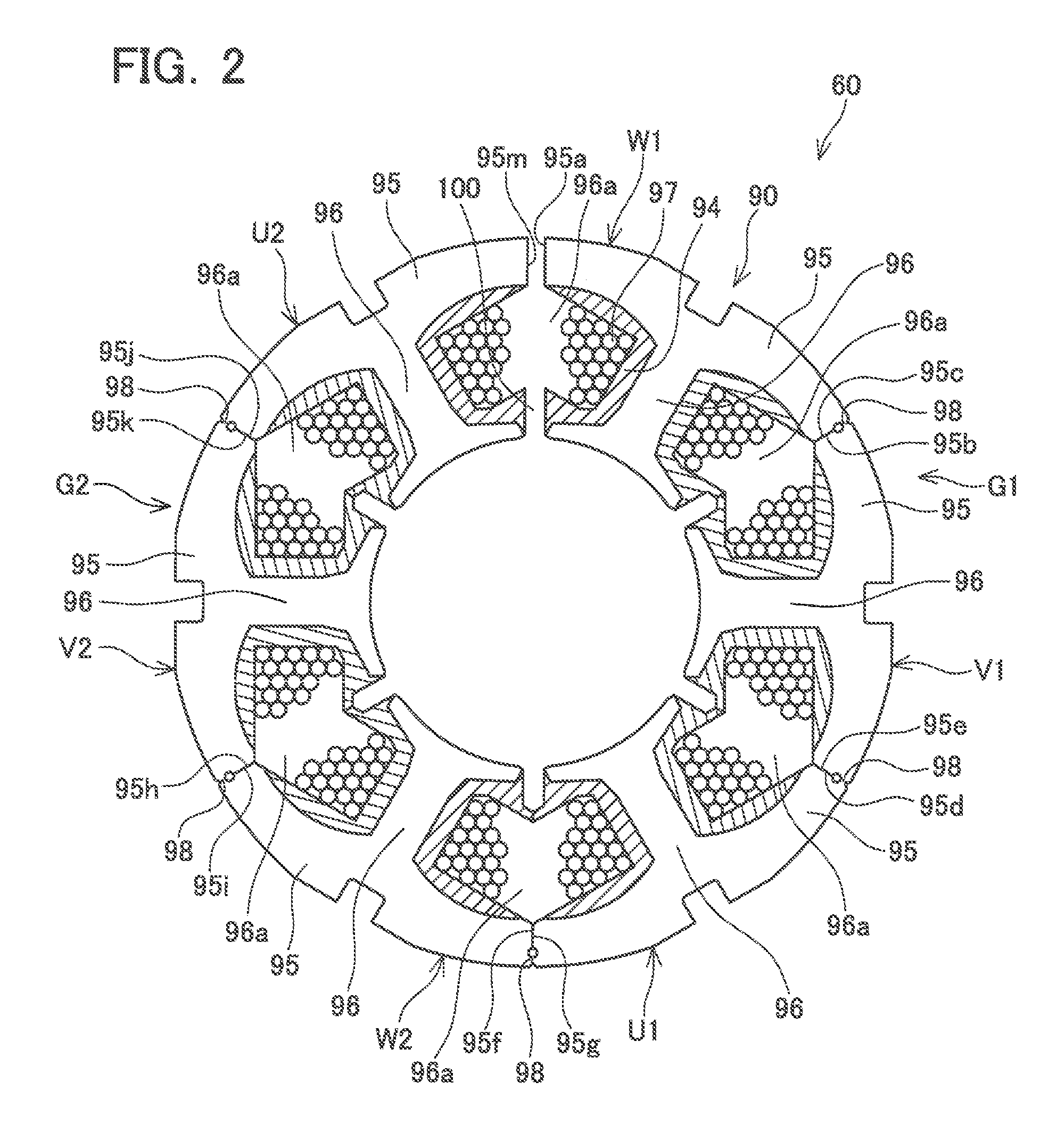
[0038]The facing surfaces 95a and 95m need not to be flat surfaces. For example, as shown in FIG. 5, the facing surface 95a of the partial core W1 may have a shape protruding in a circumferential direction of the stator 60. The facing surface 95m of the partial core U2 may have a shape recessed in the circumferential direction of the stator 60, in accordance with the facing surface 95a. As shown in FIG. 6, when the stator 60 of this modification is transformed to the tubular state from the opened state, the facing surface 95a is inserted into the facing surface 95m. In this configuration, the facing surfaces 95a and 95m, that is, the partial cores W1 and U2, can be easily positioned.

second embodiment

[0039]Compared with the first embodiment, in this embodiment, a configuration of a stator 160 is different from that of the stator 60. The difference from the first embodiment is described. As shown in FIG. 7, in this embodiment, a facing surface 195a of the partial core W1 and a facing surface 195m of the partial core U2 are respectively different from the facing surfaces 95a and 95m, in shape. The configuration of the stator 160 other than this is similar to the configuration of the stator 60.

[0040]The facing surface 195a protrudes in the circumferential direction of the stator 160 on the outer circumferential side of the stator 160. An inner circumferential surface 200a of a protruded portion of the facing surface 195a has an arc surface concentric with respect to the outer circumferential surface of the stator 160. The facing surface 195m protrudes in the circumferential direction of the stator 160 on an inner circumferential side of the stator 160. An outer circumferential surf...

third embodiment

[0043]Compared with the first embodiment, in this embodiment, a configuration of a stator 260 is different from the configuration of the stator 60. The difference from the first embodiment is described, As shown in FIG. 9, in this embodiment, a connector 298 of the partial core U1, that is, the connector 298 connecting the partial core U1 with the partial core W2, is longer than the connector 98 of the partial core U1 of the first embodiment.

[0044]As shown in FIG. 10, when the stator 260 of this embodiment is transformed to the tubular state from the opened state, the pair of facing surfaces (95a and 95m) comes into contact with each other, whereas the pair of facing surfaces (95f and 95g) is disposed with a gap in between. The configuration of the stator 260 other than this is similar to the configuration of the stator 60.

[0045]With this configuration, the connector 298 is compressed or expanded in the circumferential direction of the stator 260. Thus, the shape of the stator 260 i...


PUM


Abstract

A brushless motor may comprise a stator. The stator may comprise a core body comprising a plurality of partial cores and a coil wire. Each partial core may comprise a yoke positioned on an outer edge of the stator, teeth extending towards a rotor from the yoke, and a connector extending to an adjacent partial core from the yoke, to be connected to the yoke of the adjacent partial core. The stator may be formed to be in a tubular state by being transformed from an opened state. Each of the yokes of the partial cores may comprise a facing surface facing the yoke of the adjacent partial core. At least one set of the facing surfaces among a plurality of sets of the facing surfaces facing each other may be disposed with a gap in between in the circumferential direction of the stator.

Description

CROSS-REFERENCE TO RELATED APPLICATION[0001]This application claims priority to Japanese Patent Application No. 2013-80424 filed on Apr. 8, 2013, the contents of which are hereby incorporated by reference into the present application.[0002]1. Technical Field[0003]The present application discloses a brushless motor.[0004]2. Description of Related Art[0005]Japanese Patent Application Publication No. 2008-92691 discloses a rotating electric machine provided with a stator. The stator includes a laminated core. The laminated core includes a plurality of pole pieces that is connected with each other by connectors and linearly arranged. The stator is formed by bending the laminated core linearly arranged into a tubular shape. In the stator formed into the tubular shape, an end surface of a back yoke of each pole piece is in contact with the end surface of the back yoke of an adjacent pole piece.SUMMARY[0006]In an above-described technique, when a length of the laminated core having the pol...

Claims


Application Information

Patent Timeline
Patent Type & Authority Applications(United States)
IPC IPC(8): H02K1/14
CPCH02K1/148H02K3/325H02K15/022H02K15/095H02K7/14H02K15/12
Inventor HONDA, YOSHIHIKO
Owner AISAN IND CO LTD
Why Eureka
Try Eureka