Image recording apparatus, control method thereof, and recording medium

Active Publication Date: 2014-10-09
FUJIFILM CORP
View PDF3 Cites 6 Cited by
  • Summary
  • Abstract
  • Description
  • Claims
  • Application Information

AI Technical Summary

Benefits of technology

The present invention relates to an image recording apparatus and a control method thereof that can reduce image defects when a nozzle is found to be defective during correction processing. The technical effect of this invention is to improve the quality of inkjet printing and reduce the occurrence of image defects.

Problems solved by technology

However, in the image recording apparatus according to Japanese Patent Application Laid-Open No. 2012-071474, for example, when two defective nozzles are adjacent to each other, a sufficient ink amount or a sufficient ink dot size cannot be obtained even when the output densities of normal adjacent nozzles adjacent to the two defective nozzles are increased.
As a result, the stripe unevenness cannot be sufficiently corrected.
Depending on the design of an image such as a line drawing, there occurs an image defect that the line drawing cannot be recorded when a defective nozzle corresponding to the line drawing is made to eject no ink.

Method used


Image

  • Image recording apparatus, control method thereof, and recording medium
  • Image recording apparatus, control method thereof, and recording medium
  • Image recording apparatus, control method thereof, and recording medium

Examples


first embodiment

[Configuration of an Ink-Jet Printing System ]

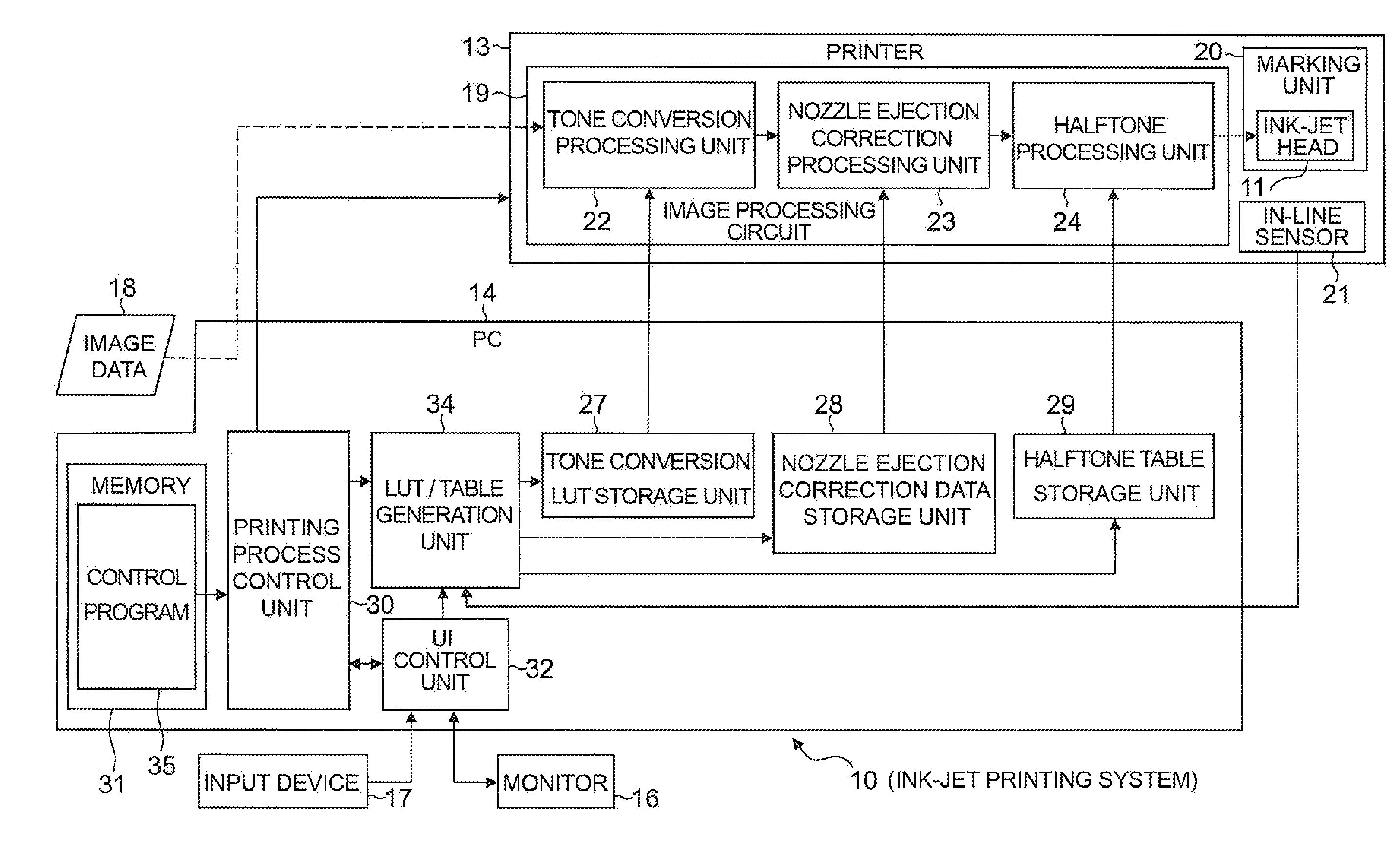
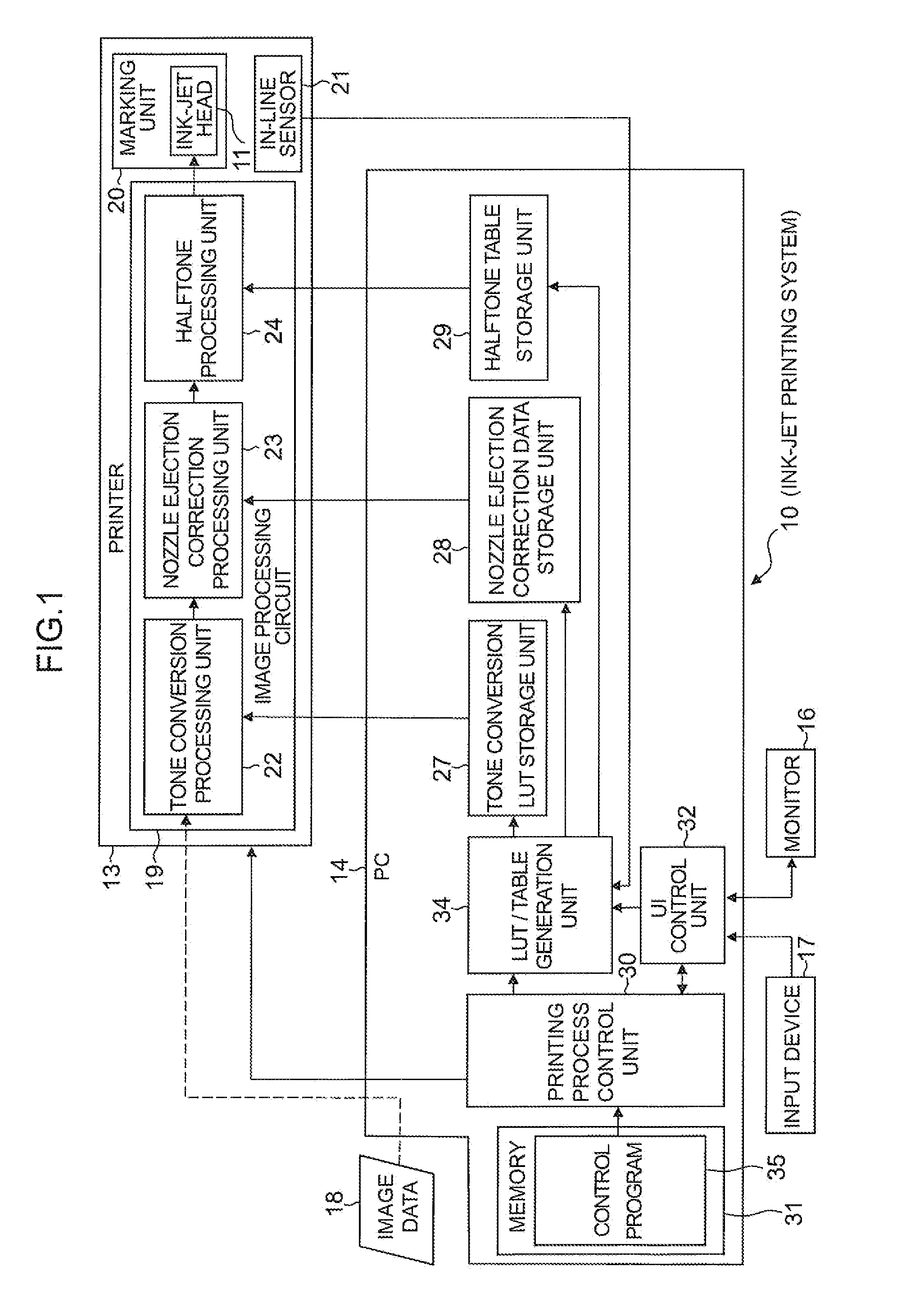
[0049]As illustrated in FIG. 1, an ink-jet printing system (simply referred to as a printing system below) 10 corresponds to an image recording apparatus in the presently disclosed subject matter. The printing system 10 records an image in a single pass method by using an ink-jet head 11 corresponding to a recording head in the presently disclosed subject matter. That is, the printing system 10 records (also referred to as forms, prints, or draws) an image on an image recording region of a recording medium 12 at a predetermined recording resolution (e.g., 1,200 dpi) by performing an operation of relatively moving the recording medium 12 (see FIG. 3) with respect to the ink-jet head 11 only once. In the present embodiment, image recording is performed by using ink of four colors: cyan (C), magenta (M), yellow (Y), and black (B). A combination of the color of ink and the number of colors is not limited to that of the present embodiment.

[00...

second embodiment

[Ink-Jet Printing System ]

[0146]Next, a printing system 10a according to a second embodiment of the presently disclosed subject matter is described by using FIG. 18. In the first embodiment, when the image recording is performed by ejecting the ink 52 from the forced ejection nozzle 25A in the non-ejection correction processing, a warning indicating that the ink 52 is ejected from the forced ejection nozzle 25A is not displayed. However, since the image recording is performed by using the forced ejection nozzle 25A, the recorded image may not always have a best image quality. Thus, when the image recording is performed by using the forced ejection nozzle 25A, the printing system 10a displays a warning to warn that the image recording is performed by using the forced ejection nozzle 25A.

[0147]The printing system 10a basically has the same configuration as the printing system 10 according to the first embodiment except that the nozzle ejection correction processing unit 23 functions a...

third embodiment

[Ink-Jet Printing System ]

[0152]Next, a printing system according to a third embodiment of the presently disclosed subject matter is described. In the aforementioned embodiments, the recording densities of the adjacent nozzles 25 respectively located on both sides of the defective nozzle 25NG (including the concentrated defective nozzles 25NGX and the forced ejection nozzle 25A) are increased in the non-ejection correction processing. The output densities of nozzles 25 around the adjacent nozzles 25 may be further increased. The printing system according to the third embodiment has the same configuration as the printing system 10 according to the first embodiment.

[0153]For example, as illustrated in FIG. 19A, when the output densities of two nozzles 25 located on each side of the defective nozzle 25NG, i.e., a total of four nozzles 25 are increased, the single width n of the non-ejection correction interference region illustrated in FIGS. 9 and 10 is defined as “the number of correc...


PUM


Abstract

A method for controlling an image recording apparatus includes: detecting a defective recording element out of a plurality of recording elements on a recording head for recording an image on a recording medium; performing a correction processing including suspension of an output of the defective recording element and increase of an output of a recording element at least adjacent to the defective recording element according to a detection result; determining whether or not an image defect is caused in the image by the suspension of output of the defective recording element, before performing the correction processing, according to the detection result; selecting a forced recording element that is forced to output ink out of defective recording elements when it is determined that the image defect is caused; and suspending the output of the defective recording element other than the forced recording element when the forced recording element is selected.

Description

BACKGROUND OF THE INVENTION[0001]1. Field of the Invention[0002]The presently disclosed subject matter relates to an image recording apparatus which can suppress occurrence of an image defect caused by a defective recording element, and a control method thereof.[0003]2. Description of the Related Art[0004]There has been known an ink-jet recording apparatus (an image recording apparatus) which forms an image on a recording medium by ejecting ink from a plurality of ink-ejecting nozzles (simply referred to as a nozzle below) provided on a recording head. In the ink-jet recording apparatus, there is generated a non-ejection nozzle which cannot eject ink due to clogging or breakdown over time. When the non-ejection nozzle as described above is generated, stripe unevenness (a white stripe or the like) caused by the non-ejection nozzle occurs in a single-pass-type ink-jet recording apparatus when a recorded image is observed. The stripe unevenness is caused not only by the non-ejection no...

Claims


Application Information

Patent Timeline
IPC IPC(8): B41J2/12
CPCB41J2/12B41J2/0451B41J2/1652B41J2/2139B41J2/2142B41J2/2146
Inventor UESHIMA, MASASHI
Owner FUJIFILM CORP
Why Eureka
Try Eureka