Image forming apparatus with multiple image forming portions and image transfers

a technology of image forming apparatus and image transfer, which is applied in the direction of electrographic process apparatus, instruments, optics, etc., can solve the problems of difficult to avoid interference phenomena in the image forming apparatus, lack of transfer current to generate defective images, etc., and achieve the effect of reducing image defects and reducing image defects

Inactive Publication Date: 2010-12-07
CANON KK
View PDF16 Cites 5 Cited by
  • Summary
  • Abstract
  • Description
  • Claims
  • Application Information

AI Technical Summary

Benefits of technology

[0023]An object of the invention is to reduce the image defect caused by the interference in the image forming apparatus provided with the image forming portion in which the surface of the image bearing member is charged with the same polarity as the toner and the image forming portion in which the surface of the image bearing member is charged in the polarity opposite the toner. Another object of the invention is to reduce the image defect caused by the interference in the image forming apparatus provided with the image forming portion which forms the toner image in the exposure region of the image bearing member and the image forming portion which forms the toner image of the non-exposure region of the image bearing member.

Problems solved by technology

It is found that the following problems are generated when the same image forming apparatus is provided with the two different process units to adopt the image multiple transfer method.
A transfer current flows to an adjacent image forming portion from a primary transfer member of an image forming portion, which creates lack of the transfer current to generate defective image.
However, as described above, it is difficult to avoid an interference phenomenon in the image forming apparatus in which the negatively charged photosensitive drum and the positively charged photosensitive drum are simultaneously used.
Unfortunately, once the transfer bias of the adjacent transfer member is turned on or off, the change in transfer current is generated to form the step in the image density.

Method used


Image

  • Image forming apparatus with multiple image forming portions and image transfers
  • Image forming apparatus with multiple image forming portions and image transfers
  • Image forming apparatus with multiple image forming portions and image transfers

Examples


first embodiment

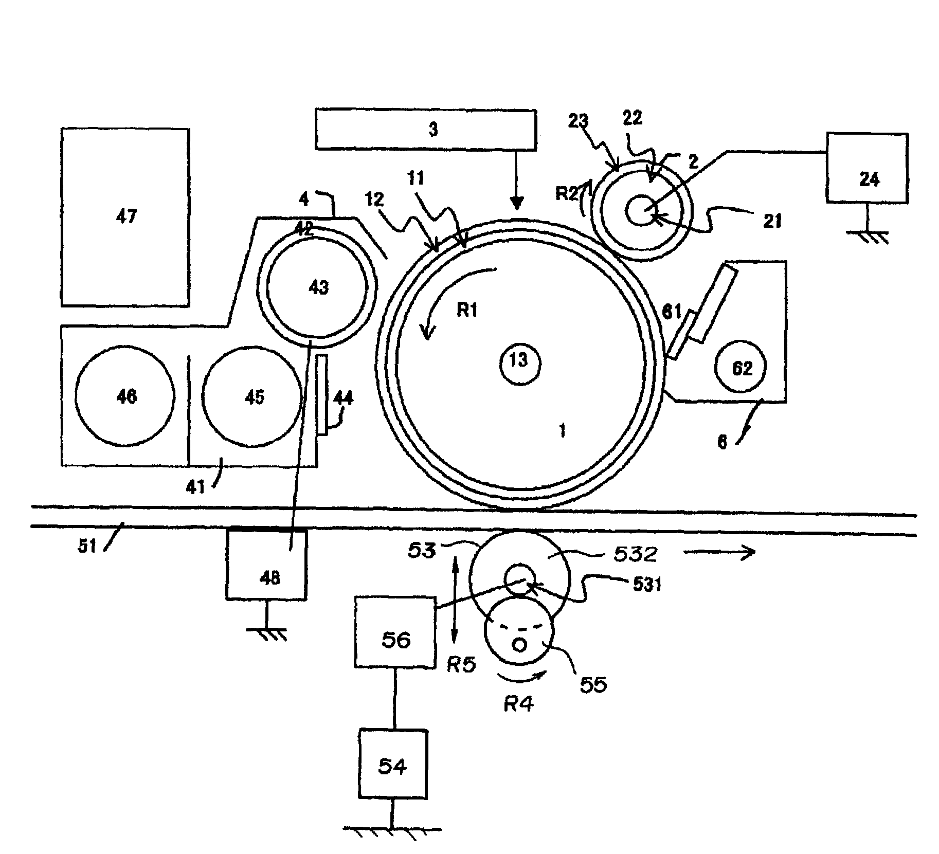
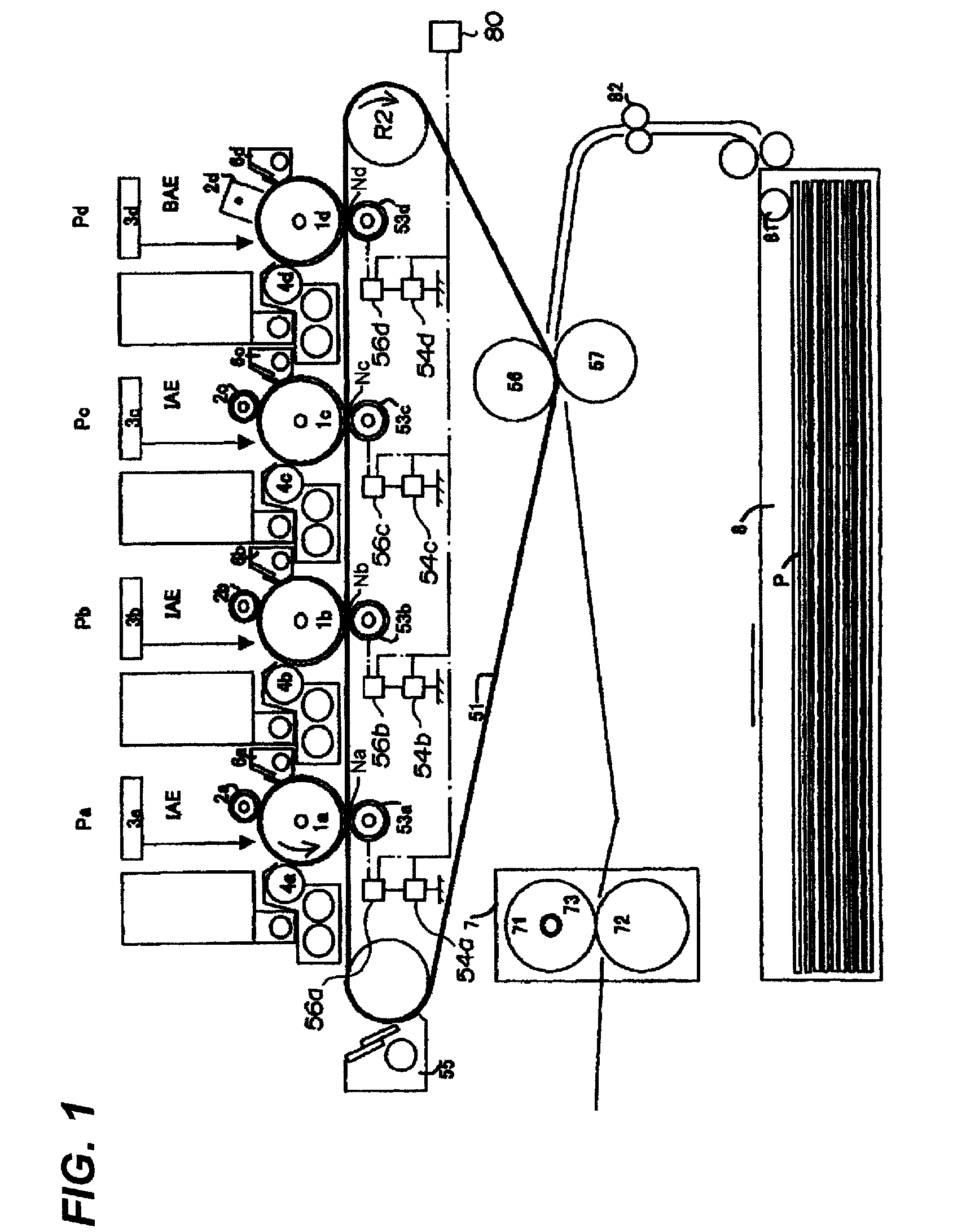
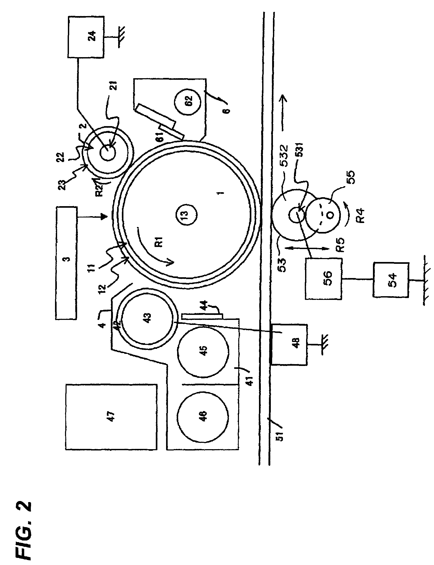
[0040]FIG. 1 shows a schematic configuration of an image forming apparatus according to a first embodiment of the invention. The image forming apparatus of the first embodiment includes four image forming portions. The image forming apparatus is a full-color electrophotographic image forming apparatus, in which toner images formed in the image forming portions are primary-transferred to an intermediate transfer member and the primary-transferred image is secondary-transferred to a recording medium to obtain a color image.

[Overall Configuration of Image Forming Apparatus]

[0041]An overall configuration of the image forming apparatus will be described. As shown in FIG. 1, process units Pa, Pb, Pc, and Pd which are of the four image forming portions are horizontally arranged to form the images of yellow Y, magenta M, cyan C, and black K colors. Photosensitive drums 1a, 1b, 1c, and 1d are arranged in the process units Pa, Pb, Pc, and Pd while being able to be rotated in an arrow directio...

second embodiment

[0083]A second embodiment of the invention is based on a transfer bias control method in the case where a lower-resistance intermediate transfer belt is used. A configuration and an operation of an image forming apparatus of the second embodiment are similar to those of the first embodiment, so that only the configuration and control different from the first embodiment will be described in detail.

[0084]In the second embodiment, a PI resin having the surface resistivity of 1011 Ω / □ (with a probe conformable to JIS-K6911, at applied voltage of 100 V for applied time of 60 sec, at 23° C. and 50% RH) and the thickness t of 100 μm is used as the intermediate transfer belt 51. The intermediate transfer belt 51 is formed by an ion-conductive belt member, and the intermediate transfer belt 51 has the advantages such as low cost and low unevenness of resistance. At the same time, a resistance fluctuates largely depending on environmental temperature and humidity, and the resistance is decrea...

third embodiment

[0091]A third embodiment of the invention is based on an apparatus in which control for setting an optimum transfer bias, called ATVC, is used in the transfer bias application is performed by the constant-voltage control. A configuration and an operation of an image forming apparatus of the third embodiment are similar to those of the first embodiment, so that only the configuration and control different from the first embodiment will be described in detail.

[0092]In the transfer roller, not only a variation in resistance is hardly suppressed during production, but also the resistance is changed by environmental temperature and humidity changes or deterioration. In ATVC, the transfer voltage is detected when the desired transfer current is passed through the transfer roller 53 at timing except for the usual image formation, and the detected transfer voltage is applied at constant during the image formation.

[0093]The third embodiment is based on the transfer bias control method for av...


PUM


Abstract

An image forming apparatus according to an exemplary embodiment of the invention includes a first image forming portion, a second image forming portion, a secondary transfer device, a transfer power supply, a controller.The first and second image forming portions include image bearing members, chargers, development devices, and transfer members.The first charger charges the first image bearing member in the same polarity as a predetermined polarity.The second charger for charging the second image bearing member in a polarity opposite the predetermined polarity.The controller controls the transfer power supply such that the transfer voltage applied to the second transfer member in the second image forming portion is not changed nor turned on and off in a period during which the toner image is transferred to the intermediate transfer member in the first image forming portion.

Description

BACKGROUND OF THE INVENTION[0001]1. Field of the Invention[0002]The present invention relates to an image forming apparatus, such as a copying machine and a printer, having a plurality image forming portions in which an image is formed by an electrophotographic system.[0003]2. Description of the Related Art[0004]An image forming method in a color image forming apparatus in which a multiple intermediate transfer method is used will be described with reference to FIG. 10.[0005]Four process units which are of electrophotographic-system image forming portions are provided according to yellow, magenta, cyan, and black colors.[0006]In FIG. 10, there are shown photosensitive drums 1a to 1d, charging means 2a to 2d, exposure means 3a to 3c, development means 4a to 4d, an intermediate transfer belt 51, primary transfer members 53a to 53d, and photosensitive drum cleaners 6a to 6d. In addition, secondary transfer members 56 and 57, and an intermediate transfer belt cleaner 55 are also shown. ...

Claims


Application Information

Patent Timeline
Patent Type & Authority Patents(United States)
IPC IPC(8): G03G15/16
CPCG03G15/0266G03G15/161G03G15/1645
Inventor MOCHIZUKI, JUN
Owner CANON KK
Why Eureka
Try Eureka