Rotary developing device

a developing device and rotary technology, applied in the direction of instruments, electrographic process equipment, optics, etc., can solve the problems of increasing the load on the cpu, restricting the entire operation of the apparatus, and poor positioning accuracy of dc brushless motors, so as to reduce vibration, damp vibration, and transfer error

Inactive Publication Date: 2005-02-24
SEIKO EPSON CORP
View PDF3 Cites 6 Cited by
  • Summary
  • Abstract
  • Description
  • Claims
  • Application Information

AI Technical Summary

Benefits of technology

[0019] It is an object of the present invention to quickly damp vibration generated according to the rotation of a rotary developing unit and the rotation of development rollers. It is another object of the present invention to avoid a collision of tooth tops between gears which may occur due to switching between the rotary unit driving action and the development member driving action and damp the impact generated by the collision, thereby reducing vibration and transferring error. It is still another object of the present invention to shorten the time for switching between the rotary unit driving action and development member driving action and prevent the generation of vibration, thereby reducing image defects and image deterioration resulting from registration error.

Problems solved by technology

When a DC brushless motor, not a stepping motor, is used for driving the rotary developing unit, an encoder is fixed to the output shaft of the motor because the DC brushless motor has poor positioning accuracy.
In addition, the DC brush less motor has poor acceleration.
The increase in load on the CPU restricts the entire operation of the apparatus.
However, even stepping motor has problems such as vibration, noise, and smaller flexibility for load fluctuation.
In addition, stepping motor is expensive as compared to other motors such as DC brushless motor relative to the same torque.
During this, the pitch circles of the gears meet so that their tooth tops may collide with each other in some cases.
In the event of collision, the driving means may develop trouble (may stop due to breakdown of the motor) and may produce image defects due to vibration generated by the collision.
In this case, the vibration produces registration error during formation of latent image.
In this case, the vibration produces transferring error.
Further, when a driving means for rotating the development roller starts to operate just after the rotary developing unit is stopped, uneven rotation of the driving means or vibration generated in the driving means is transmitted to the entire device.
Similar to the vibration generated at the stop of the rotary developing unit, the vibration after the stop of the rotary developing unit produces image defects such as registration error.
These vibrations may not damp each other and may be sometimes superposed to be synthesized i.e. amplified, thus producing image defects such as errors in longer period.
However, once the retention of the rotor is cancelled, the position of the rotor should be unstable.
In this case, the position of the first exciting phase for the next action for driving the development roller is not certain, causing position error and thus reducing the rotational accuracy of the rotary developing unit.
However, the retention of the rotor requires the consumption of electric power.
The increase in temperature leads to drop in torque.
In the rotary developing unit, the amounts of developers in the respective developer cartridges vary according to the development operation so that the load balance of the cylinder varies delicately.
Addition of such drivers and timers makes the substrate structure complex and also makes the control, including the control of the CPU, complex.
It should be understood that the addition of such drivers and timers increases superposed driving time, leading to increase in electrical consumption.

Method used


Image

  • Rotary developing device
  • Rotary developing device
  • Rotary developing device

Examples


Embodiment Construction

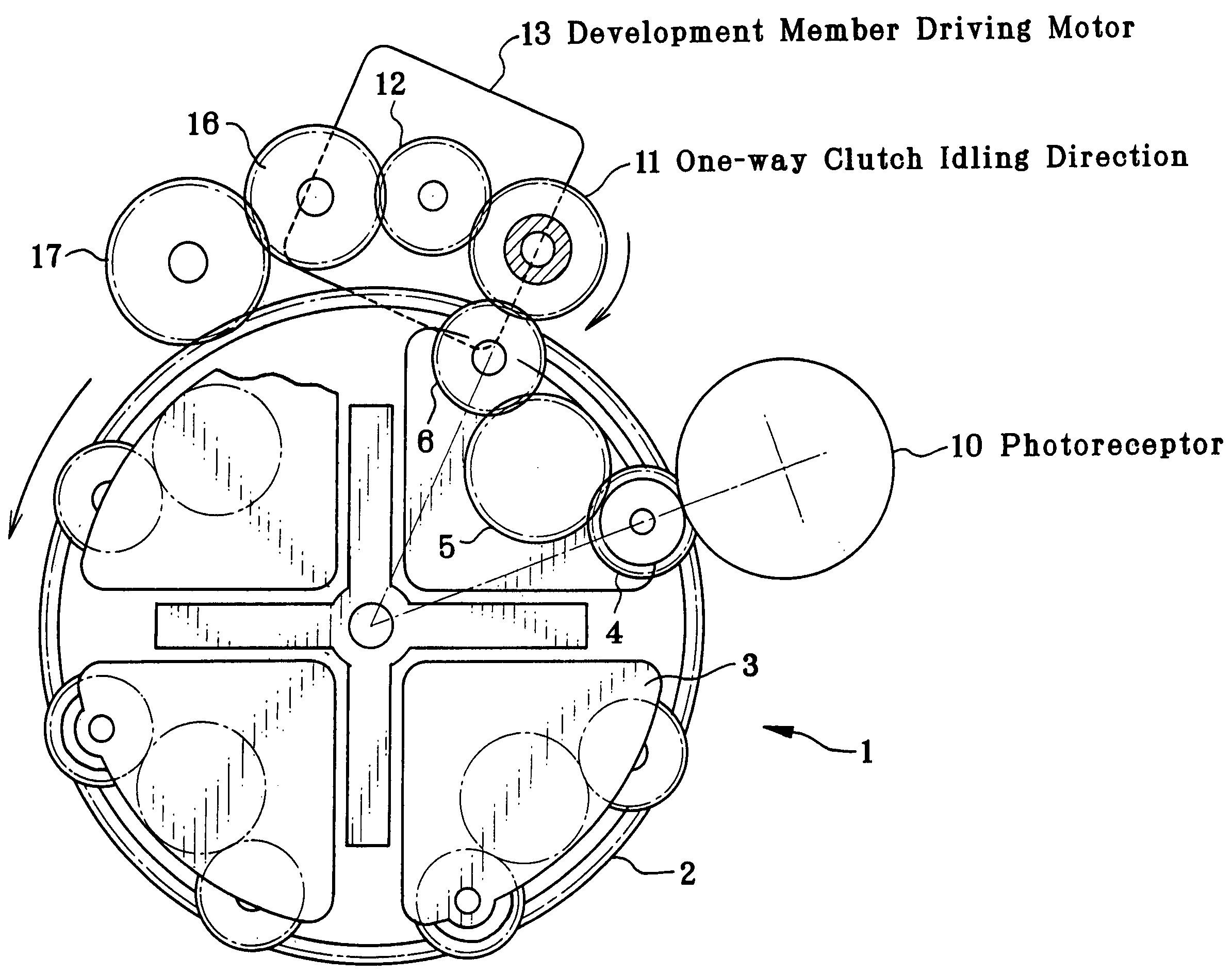
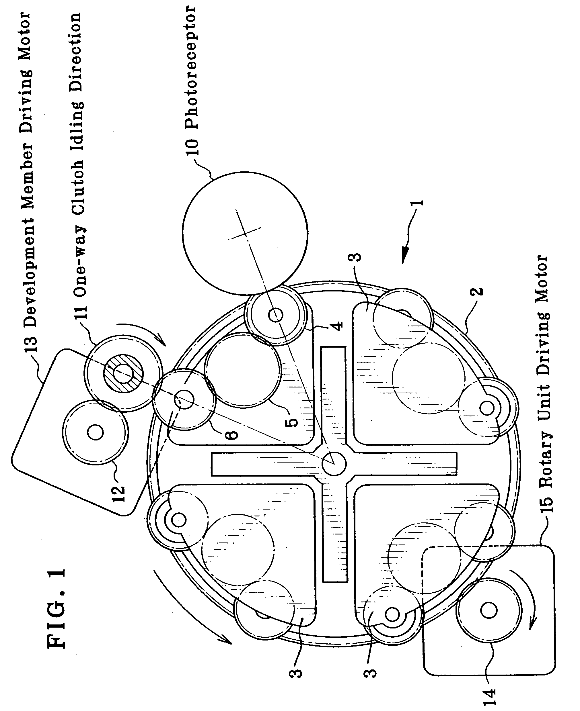
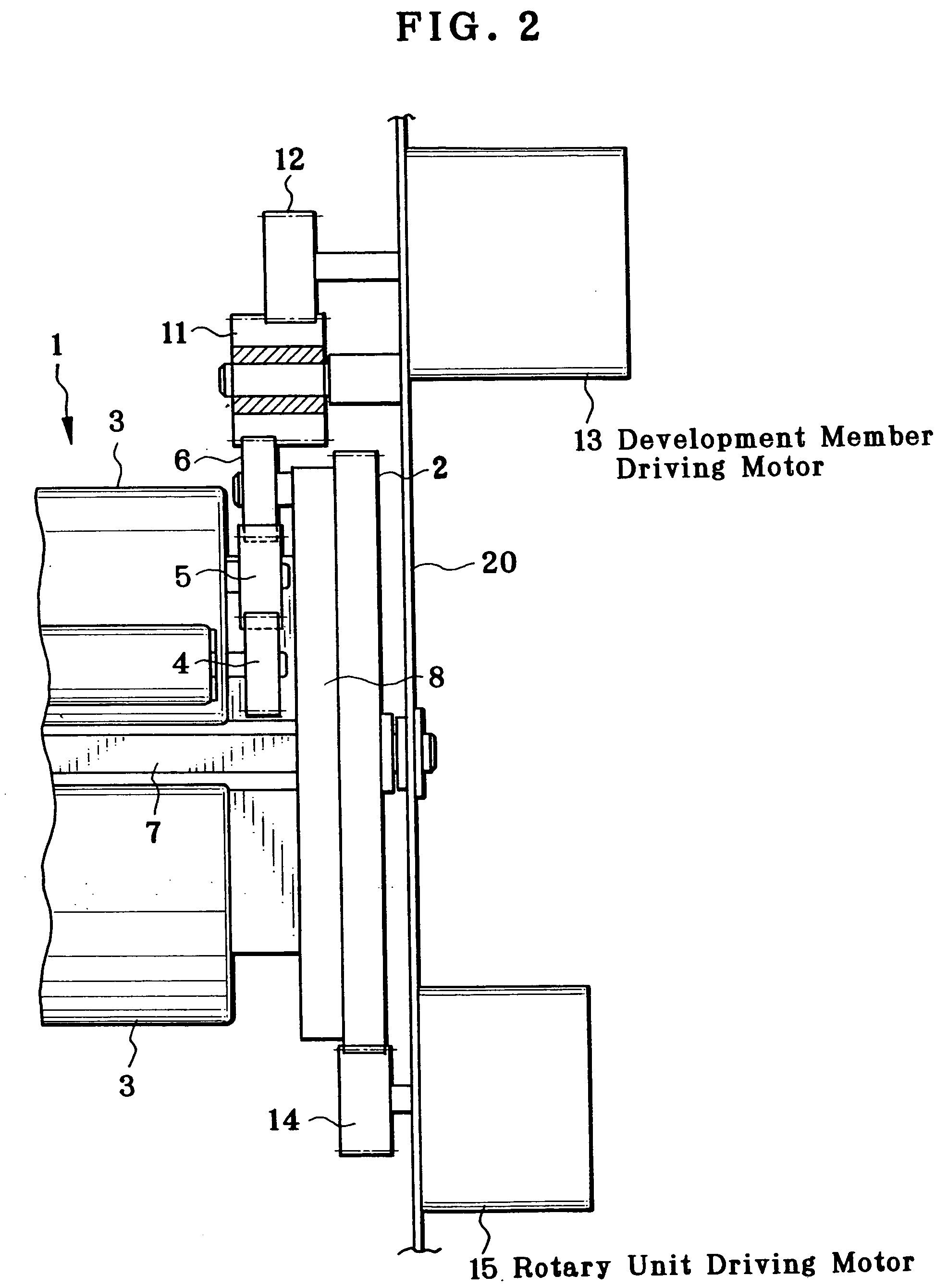
[0043] Hereinafter, embodiments of the present invention will be described with reference to the drawings. FIG. 1 is an illustration showing an embodiment of a rotary developing device according to the present invention, FIG. 2 is a side view of a gear train section of the rotary developing device. In these drawings, numeral 1 designates a rotary developing unit, 2 designates a rotary input gear, 3 designates each development cartridge, 4 designates a development roller gear, 5 designates each idle gear, 6 designates a development input gear, 10 designates a photoreceptor, 11 designates a development member driving gear, 12 designates a motor pinion, 13 designates a development member driving motor, 14 designates a motor pinion, and 15 designates a rotary unit driving motor.

[0044] In FIG. 1, the rotary developing unit 1 has a substantially cylindrical shape and is provided around its periphery with a plurality of development cartridges 3 to develop latent images formed on a latent ...


PUM


Abstract

A rotary developing device having a cylindrical rotary developing unit, and a plurality of development members mounted around the periphery of the rotary developing unit. The rotary developing unit is driven to bring one of the development members to the developing position facing a photoreceptor and subsequently the transmission of the driving power to the development member is conducted. In the rotary developing device, the driving direction of the development members at a driving power transmitting section is set to be the same as the driving direction of the rotary developing unit and a simple additional structure employing an electromagnetic clutch or a one-way clutch is applied to the driving power transmitting section, thereby avoiding a collision of tooth tops between gears, damping the impact generated by a collision, and reducing vibration and damage of tooth tops. Therefore, the production of image defects due to registration error are prevented.

Description

BACKGROUND OF THE INVENTION [0001] The present invention relates to a rotary developing device comprising a cylindrical rotary developing unit, a plurality of development members mounted around the periphery of said rotary developing unit, and a driving means, wherein the rotary developing unit is driven by the driving means to bring one of the development members to the developing position facing a photoreceptor and subsequently the transmission of the driving power to the development member is conducted [0002] In a conventional multi-color image forming apparatus employing a rotary development method, a plurality of development members are mounted along the periphery of a rotary developing unit and the rotary developing unit is driven to sequentially bring the development members to a developing position so as to carry out the development operation. For this, a driving means for rotating the rotary developing unit and a driving means for rotating a development roller or the like b...

Claims


Application Information

Patent Timeline
Patent Type & Authority Applications(United States)
IPC IPC(8): G03G15/01
CPCG03G2215/0177G03G15/0126
Inventor KISHIGAMI, MINORU
Owner SEIKO EPSON CORP
Why Eureka
Try Eureka