Device and method for aligning containers

a container and device technology, applied in the field of devices for aligning containers, can solve the problems of insufficient accuracy or reliability, the inability to determine the actual rotary position of the container, and the inability to determine the position and/or rotary position of a relief-like feature on the container surface, etc., to achieve space-saving and precise labeling operation, reduce measurement errors, and minimize the error of the accessed target rotary position

Active Publication Date: 2015-12-01
KRONES AG
View PDF21 Cites 5 Cited by
  • Summary
  • Abstract
  • Description
  • Claims
  • Application Information

AI Technical Summary

Benefits of technology

[0014]According to a particularly advantageous embodiment of the device according to the present disclosure, the evaluation unit is configured such that it is capable of creating from the image data of the at least two views a virtual view of the container. An idealized image of the container with reduced image defects can be calculated in this way. This allows the position and / or the rotary position of features on the surface of the container to be determined with higher accuracy and reliability. Also a plurality of virtual views may here be combined so as to obtain a panorama view of the container.
[0027]The posed task is additionally solved by a labeling method comprising the method for aligning containers according to the present disclosure as well as a step of labeling the containers, wherein the accessed target rotary position is a starting position and / or reference position for labeling. This allows a particularly space-saving and precise labeling operation while avoiding an application of labels to regions with raised and / or recessed surface areas.

Problems solved by technology

1. In the case of comparatively small features, such as a molding seam on the surface of the container, the contours of the feature will only cause comparatively weak differences in contrast in the reflected incident light. This may perhaps not suffice for allowing an exact determination of the position of the feature, in particular when an only weakly contoured feature is seen in a view that is substantially a front view. Hence, the actual rotary position of the container cannot be determined, or only be determined with insufficient accuracy on the basis of said feature.
2. Contours of elevated features are shown with different contrast differences and / or edge widths at different rotary positions, i.e. at different object angles. Also this may have the effect that the position and / or the rotary position of a relief-like feature on the container surface can be determined only with insufficient accuracy or reliability.
3. In the areas of the features to be identified, the diameter of the container may exhibit certain tolerances, which result from the manufacturing process and which are relevant to position determination. Depending on the dimensional accuracy of the container to be examined, this may lead to an object angle-dependent inaccuracy in the determination of the position or rotary position of the identified feature. Therefore, it may be impossible to calculate a correct correction angle for moving the container to a target rotary position for subsequent labeling.
In addition to the considerable complexity of equipment and the large amount of time required, the problems specified under 1 and 2 can, however, not be solved or may even be aggravated by this course of action.

Method used


Image

  • Device and method for aligning containers
  • Device and method for aligning containers

Examples


Embodiment Construction

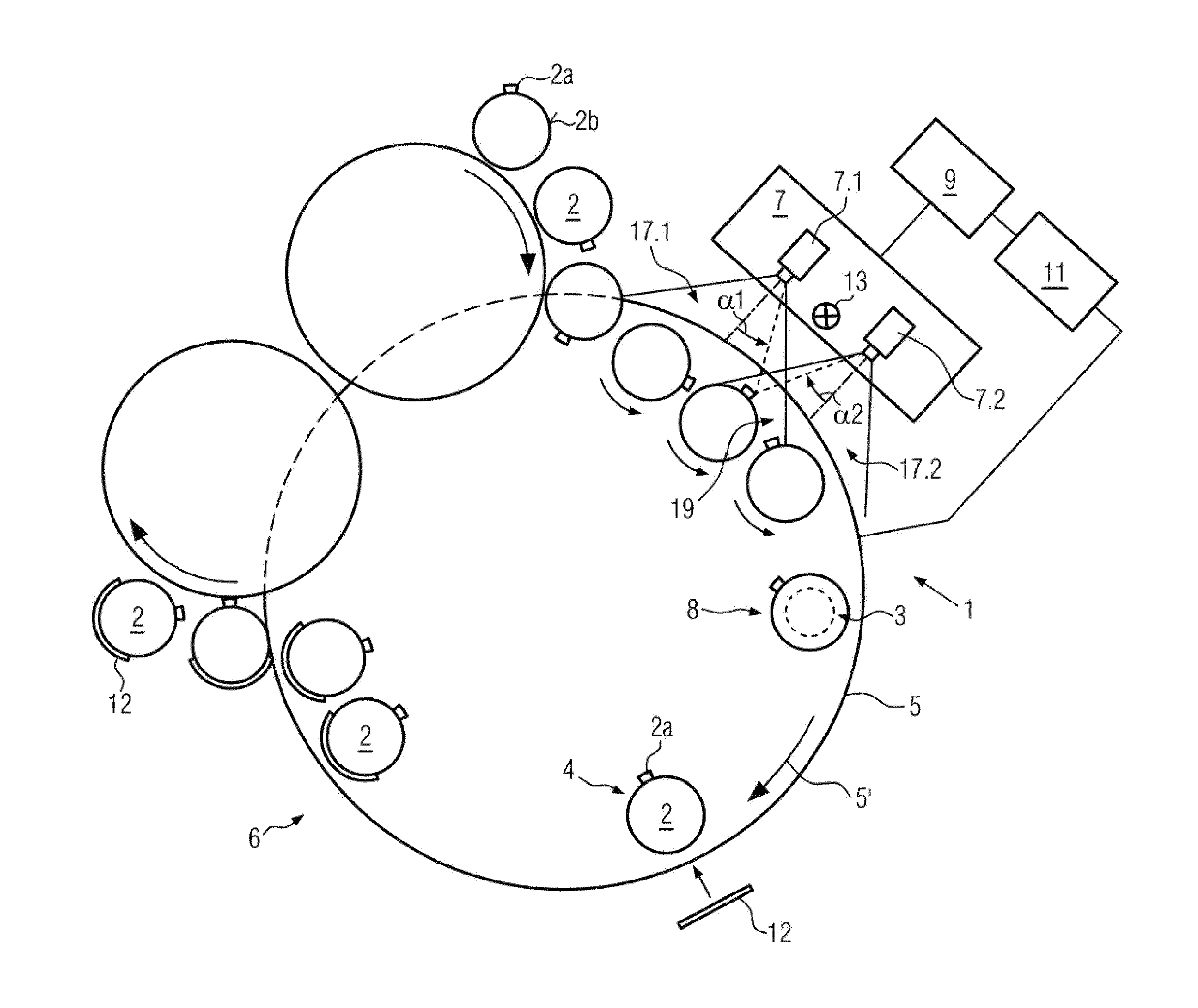
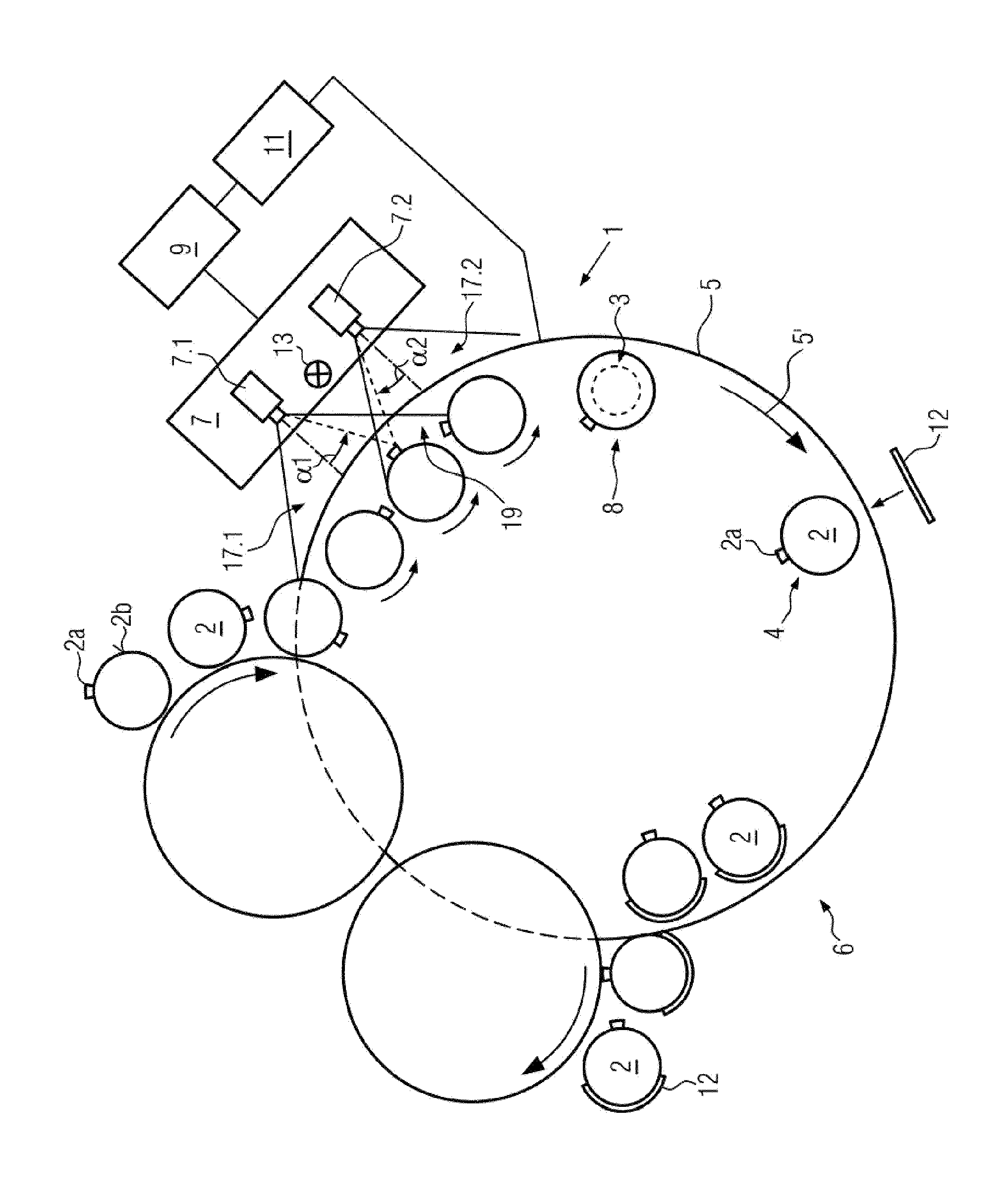
[0029]As can be seen from the only FIGURE, which shows a schematic top view, a preferred embodiment of the device 1 for aligning containers 2, such as beverage bottles or the like, according to the present disclosure comprises a plurality of rotatable holders 3 for receiving, holding and aligning the containers 2 so as to bring them into a target rotary position 4 for a subsequent processing step, in particular for labeling the containers 2. The holders 3 comprise e.g. turntables or the like, which are concealed in the FIGURE by the respective containers 2. The containers 2 move along a conveying path 5, which may e.g. be a constituent part of a carousel-like labeler 6, along a camera system 7 oriented substantially tangentially to the conveying path 5. In the course of this movement, the containers 2 are rotated about their main axis and imaged, preferably in a full-circumference imaging mode, at different rotary positions. The respective actual rotary positions 8 of the containers...


PUM

PropertyMeasurementUnit
object anglesaaaaaaaaaa

Abstract

A device and a method for aligning containers including an evaluation unit, which is capable of determining the position and / or the rotary position of at least one feature of the surface of containers to be aligned, by calculating image data of said feature in at least two views that differ with respect to the imaged rotary position of the containers, and where picture distortions and contrast limitations caused by the perspective can be compensated. The reliability of rotary position recognition and correction can thus be improved when aligning the containers.

Description

CROSS-REFERENCE TO RELATED APPLICATION[0001]The present application is the United States national phase of International Patent Application No. PCT / EP2012 / 063584, filed Jul. 11, 2012, which application claims to German Application No. DE 10 2011 083 377.3 filed Sep. 26, 2011. The priority application is hereby incorporated by reference.FIELD OF THE DISCLOSURE[0002]The present disclosure relates to a device for aligning containers, a corresponding method for aligning containers, a labeling machine and a labeling method.BACKGROUND[0003]Before containers, such as beverage bottles, are labeled, they are normally moved to an appropriate target rotary position with respect to the labeling device in question. To this end, it is known e.g. from DE 10 2005 050 902 A1 and DE 10 2009 020 919 A1 to conduct the containers, while they are rotating about their main axis, past a camera system so as to image the whole circumference of the containers in a plurality of camera pictures for identifying ...

Claims


Application Information

Patent Timeline
Patent Type & Authority Patents(United States)
IPC IPC(8): G01N21/90B65C9/06B65G47/244
CPCB65C9/06B65G47/244B65C9/067G01N21/9036
Inventor KOLB, HERBERT
Owner KRONES AG
Why Eureka
Try Eureka