Image forming apparatus

Active Publication Date: 2015-04-30
CANON KK
View PDF4 Cites 0 Cited by
  • Summary
  • Abstract
  • Description
  • Claims
  • Application Information

AI Technical Summary

Benefits of technology

The present invention aims to minimize picture flaws caused when using a method called PWM to expose a background.

Problems solved by technology

This causes a gap between the color belts in a final image on a recording medium, resulting in degradation in image quality. FIG. 19 is a diagram illustrating a state in which white gaps are generated, showing the state of an electric field between a photosensitive drum and a developing roller.
However, the background exposure based on PWM can generate image defect depending on the allocation of an emission period for normal exposure for toner adhesion and an emission period for background exposure for preventing toner adhesion.
In other words, simply placing the emission period for background exposure in an emission period not for normal exposure, which corresponds to a white portion of the image, can cause exposure light during the emission period for background exposure to interfere with exposure light during light emission for normal exposure.
Such interference decreases the potential of an area of the photosensitive member between the area corresponding to the emission period for normal exposure and the area corresponding to the emission period for background exposure.
Thus, the potential of the sandwiched area decreases to an exposure level at which toner adheres, so that an area in which toner adheres finally unintentionally increases in size.
This can cause image defect.

Method used


Image

  • Image forming apparatus
  • Image forming apparatus
  • Image forming apparatus

Examples


first embodiment

Image Forming Apparatus

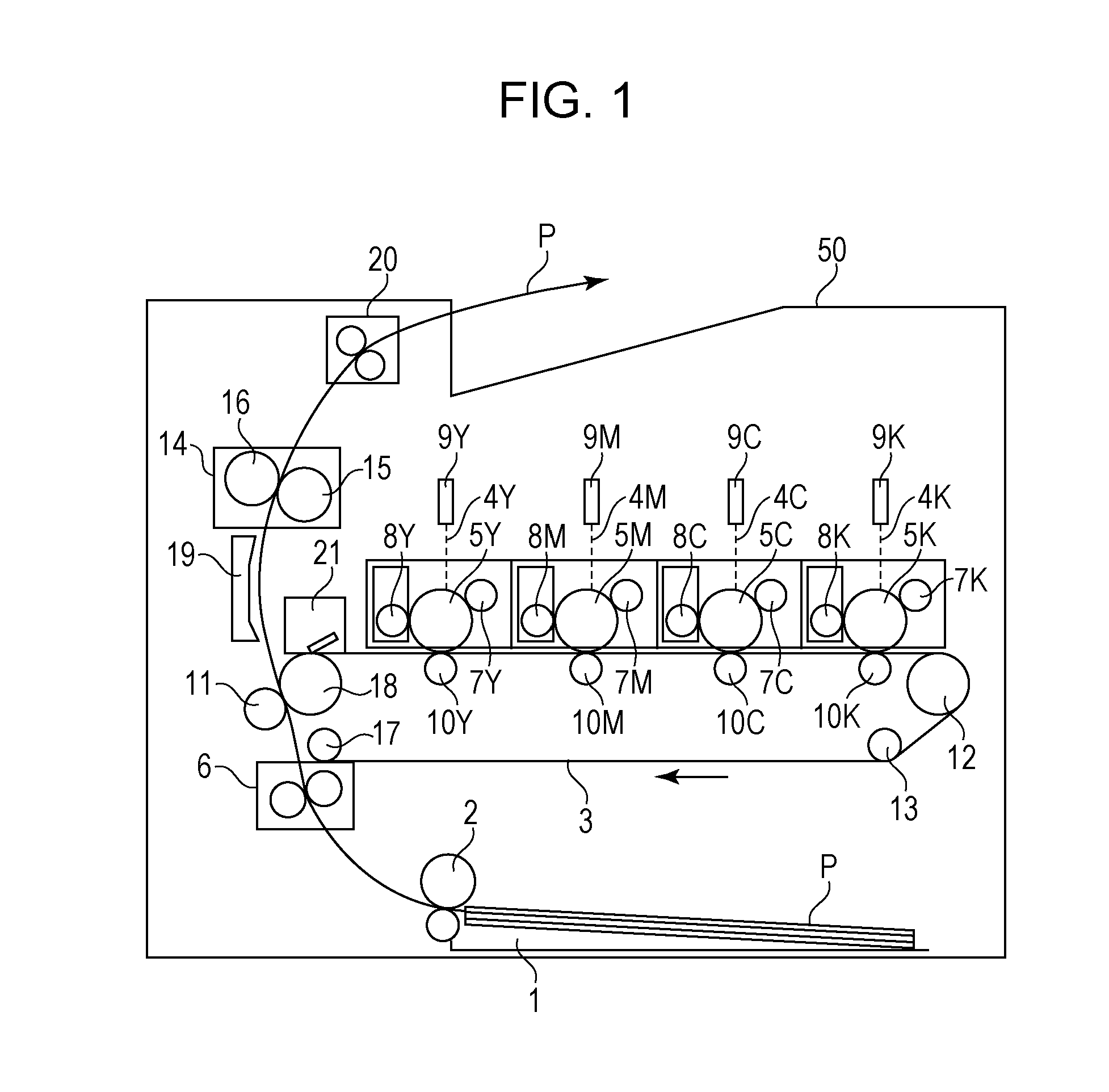
[0039]FIG. 1 is a schematic configuration diagram of a color laser printer (an image forming apparatus) according to a first embodiment of the present invention. As illustrated, a color laser printer 50 is a four-drum tandem system (in-line system) printer including photosensitive drums 5 (5Y, 5M, 5C, and 5K) which are photosensitive members. This image forming apparatus is a printer with a resolution of 600 dpi and a speed of 20 ppm corresponding to A4-size paper (210 mm×297 mm).

[0040]Around the photosensitive drums (photosensitive members) 5 (5Y, 5M, 5C, and 5K), charging rollers (charging devices) 7 (7Y, 7M, 7C, and 7K), developing rollers (developing devices) 8 (8Y, 8M, 8C, and 8K), exposure devices 9 (9Y, 9M, 9C, and 9K), and primary transfer rollers (primary transfer devices) 10 (10Y, 10M, 10C, and 10K) are disposed, respectively.

[0041]An intermediate transfer belt 3 is an endless belt, which is stretched round a drive roller 12, a tension roller 13, an ...

second embodiment

[0090]The configuration of an image forming apparatus according to a second embodiment of the present invention will be described. The same components as those in the first embodiment are given the same reference signs, and descriptions thereof will be omitted. Since an image forming system, an image processing unit, and an image processing flow are the same as those of the first embodiment, detailed descriptions thereof are omitted. In this embodiment, degradation in image quality is prevented more stably by performing image processing using different position control matrices for level 0 and levels 1 to 31 to attain more uniform background exposure.

Image Processing Flow

[0091]FIG. 12 is a diagram illustrating the order of growth of pixels constituting a dither matrix. FIG. 13 is a table showing the levels of gray (levels 1 to 31) of individual pixels constituting the dither matrix and threshold values set for the levels. The halftone processing section 501a performs the same proces...


PUM


Abstract

An image forming apparatus includes a signal generating unit that stores information on a plurality of dither matrices preset in correspondence with the density level of toner to be attached to the photosensitive member and converts input image data based on the dither matrices to generate a driving signal. The signal generating unit stores information on a first dither matrix corresponding to a first density level and a second dither matrix corresponding to a second density level higher than the first density level. The first dither matrix includes a minute exposure area in which the exposure device is caused to emit light to attain a potential at which no toner adheres to the photosensitive member, and the second dither matrix includes a normal exposure area in which the exposure device is caused to emit light to attain a potential at which toner adheres to the photosensitive member.

Description

BACKGROUND OF THE INVENTION[0001]1. Field of the Invention[0002]The present invention relates to an image forming apparatus using an electrophotographic process, such as a laser beam printer, a copying machine, or a facsimile.[0003]2. Description of the Related Art[0004]A method for forming a color image with an electrophotographic image forming apparatus is known by which a color image is formed by overlapping images of a plurality of colors by repeating a process of transferring a toner image formed on a photosensitive drum through charging, exposure, and development onto a recording medium a plurality of times. It is known that a phenomenon occurs in such a color-image forming apparatus in which white gaps, which should not be present, are generated between adjacent images of different colors occurs. This phenomenon is hereinafter referred to as white gap. This phenomenon occurs when a visualized image thinner than an electrostatic latent image formed on the photosensitive drum i...

Claims


Application Information

Patent Timeline
IPC IPC(8): G06F3/12
CPCG03G15/043G03G2215/0431
Inventor IIDA, KENICHISHIMIZU, YUSUKETAKAYAMA, TOSHIHIKOMORIHARA, RYO
Owner CANON KK
Why Eureka
Try Eureka