
Camera module for vehicle

Inactive Publication Date: 2014-10-09
LG INNOTEK CO LTD
View PDF21 Cites 21 Cited by
  • Summary
  • Abstract
  • Description
  • Claims
  • Application Information

AI Technical Summary

Benefits of technology

The camera module for vehicles described in this patent is designed with a simplified assembly process. The fixing unit is formed at the same time as the cover member, eliminating the need for a separate bracket to keep the module in place. This reduces the time and effort required to assemble the camera module.

Problems solved by technology

In this instance, there occurs a problem where the camera module cannot capture an image clearly, even if the optical axis is precisely aligned inside the camera module.
Furthermore, a separate bracket is disadvantageously needed to additionally increase a unit price of the bracket, and a mold manufacturing cost for manufacturing the bracket.

Method used


Image

  • Camera module for vehicle
  • Camera module for vehicle

Examples


Embodiment Construction

[0027]Now, the camera module for vehicle according to exemplary embodiments of the present invention will be described in detail with reference to the accompanying drawings.

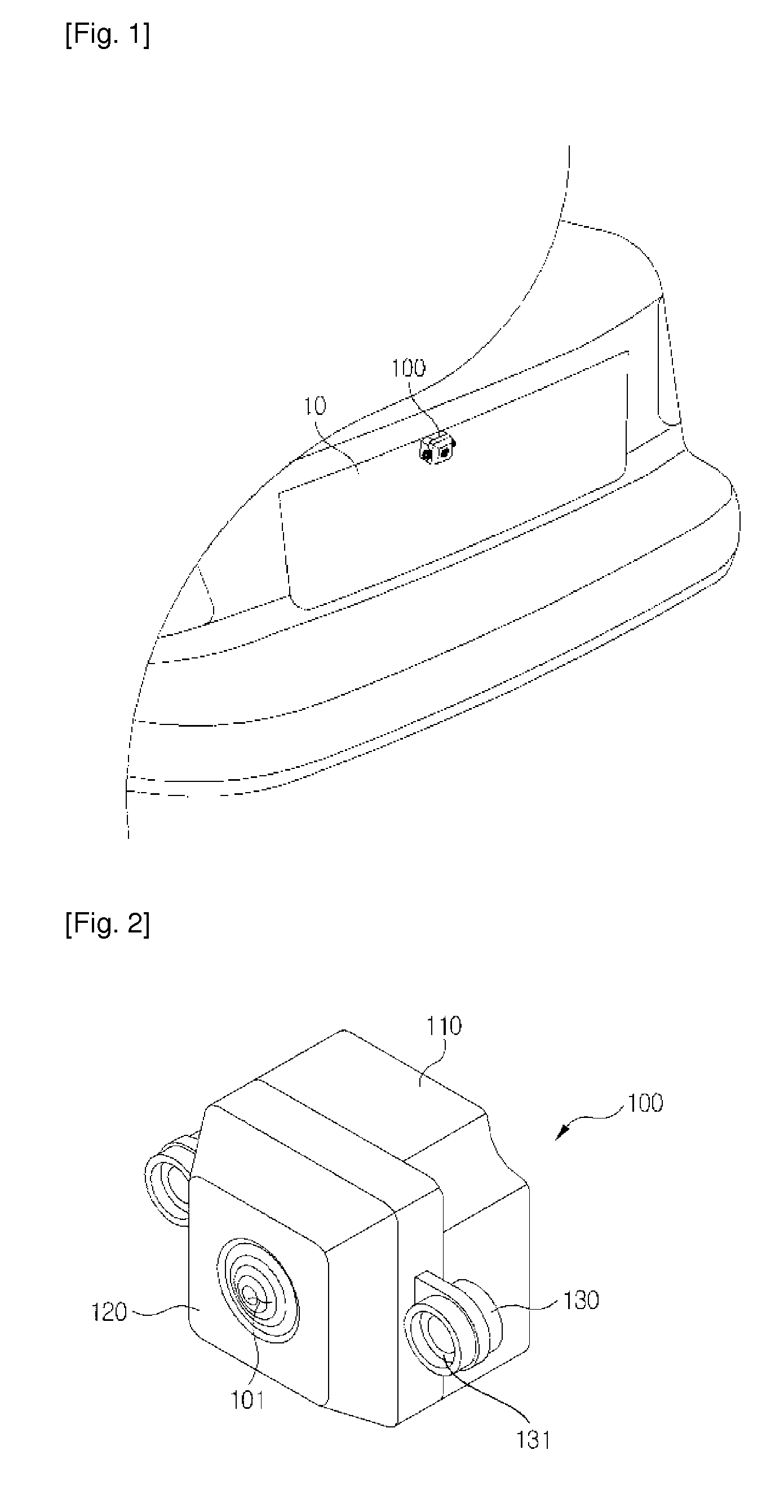
[0028]FIG. 1 is a schematic view illustrating a state where a camera module is installed on a vehicle according to an exemplary embodiment of the present invention, and

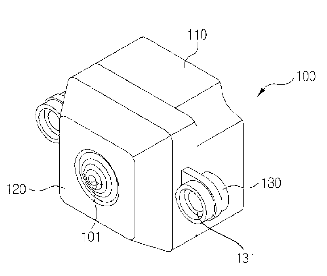
[0029]FIG. 2 is a perspective view illustrating the camera module of FIG. 1.

[0030]Referring to FIG. 1, a vehicle body is generally provided at a rear surface with a rear garnish for installing a vehicle emblem or a handle for opening a trunk, and a camera module (100) for vehicle may be provided near the rear garnish for monitoring a rear side of the vehicle, when necessary.

[0031]Recently, a variety of equipment is installed on a vehicle for improvement of user convenience, and a camera module for vehicle (herein after referred to as vehicle camera module) captures a dead zone where a driver s view fails to reach, and provides the driver with image...


PUM


Abstract

A camera module is provided, the camera module including a camera module body (110) for installing an image sensor therein, a cover member (120) coupled to an upper side of the camera module body (110), and a fixing unit (130) integrally formed with the cover member (120) to fix the cover member and the camera module body to the vehicle.

Description

TECHNICAL FIELD[0001]The teachings in accordance with exemplary embodiments of this invention relate generally to a camera module.BACKGROUND ART[0002]Recently, a camera module is widely and frequently used for obtaining an image by the influence of sophistication and automation of vehicular parts. For non-limiting examples, camera modules are used for front and rear monitoring cameras and for black boxes in vehicles. In order to install a camera module at a front or a rear side of a vehicle, a separate bracket member for arranging the camera module on a proper position of the vehicle must be provided.[0003]Structures for fixing a camera are known in the art. For example, Korea Laid-Open Patent Application No. 2010-0000956 discloses a structure configured to fix a camera. The structure, albeit not a configuration for fixing a camera module, includes a configuration for installing an angle-adjustable camera using a bracket. Furthermore, Korea registered Patent No.: 10-0912082 (registe...

Claims


Application Information

Patent Timeline
IPC IPC(8): H04N5/225H04N7/18
CPCH04N7/183H04N5/2251B60R11/04B60R2011/004H04N23/51H04N23/50H04N23/00
Inventor HAN, SANG YEAL
Owner LG INNOTEK CO LTD
Learn More