Football Throwing System and Method of Operation

Inactive Publication Date: 2014-10-16
DEESE JULIAN
View PDF3 Cites 14 Cited by
  • Summary
  • Abstract
  • Description
  • Claims
  • Application Information

AI Technical Summary

Benefits of technology

[0018]It is another object of the present invention to provide a football throwing system that can be operated without close supervision by a coach, so that the coach is free to more actively participate in football practice.
[0020]Another object of the present invention is to provide a football throwing system that can throw a series of footballs without the need for an operator to manually load footballs into the football throwing device.
[0021]Yet another object of the present invention is to provide a football throwing system that displays a visual representation of the route selected by the user so as to enable the user to visualize the pattern to be executed.
[0022]Another object of the present invention is to provide a football throwing system that may be readily fabricated from materials that permit relative economy and are commensurate with durability.

Problems solved by technology

Paulson et al. does not disclose a football throwing device having a processor and a means for automatically adjusting the launch variables of the device.
Further, Paulson et al. does not disclose a user input system.
Paulson does not disclose a system for automatically adjusting the launch variables of a football throwing device, nor does Paulson disclose a football throwing device having a user input system.
Osojnak does not provide a system that accepts user input, and requires an operator to control the function of the machine.
Fenley does not disclose a football throwing system that is automated and that can adjust its orientation based upon input from the user.
This limits the availability of the operator, generally a football coach, to engage in other activities and more actively participate in a football practice.

Method used


Image

  • Football Throwing System and Method of Operation
  • Football Throwing System and Method of Operation
  • Football Throwing System and Method of Operation

Examples


Embodiment Construction

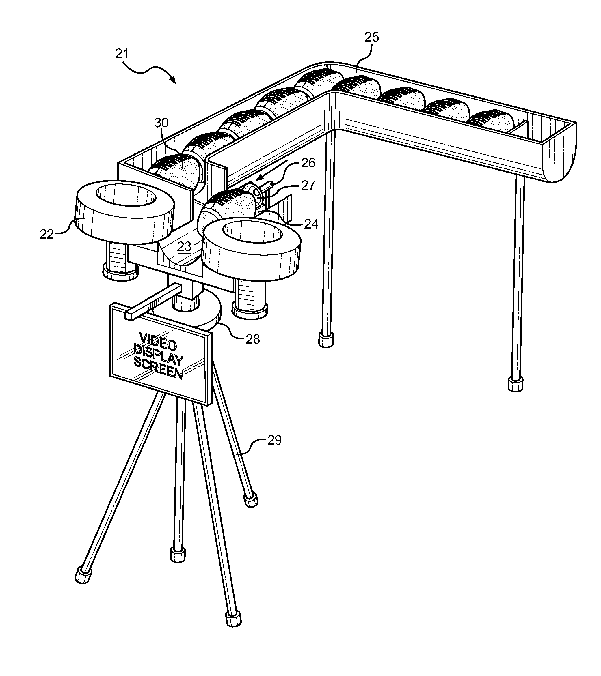
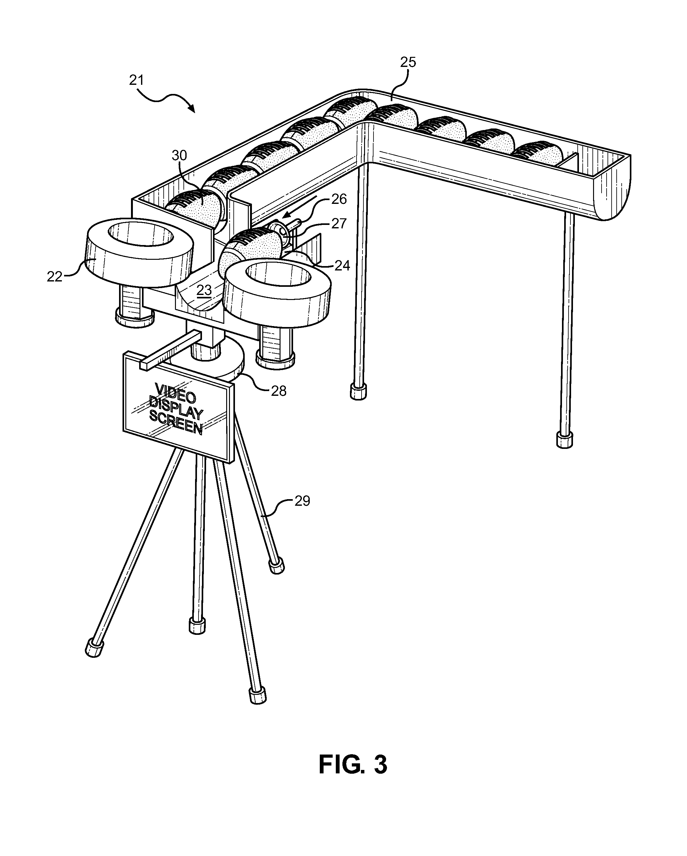
[0032]Reference is made herein to the attached drawings. Like reference numerals are used throughout the drawings to depict like or similar elements of the football throwing system. For the purposes of presenting a brief and clear description of the present invention, the preferred embodiment will be discussed as used for automatically adjusting a football throwing device in accordance with a route selected by a user. The figures are intended for representative purposes only and should not be considered to be limiting in any respect.

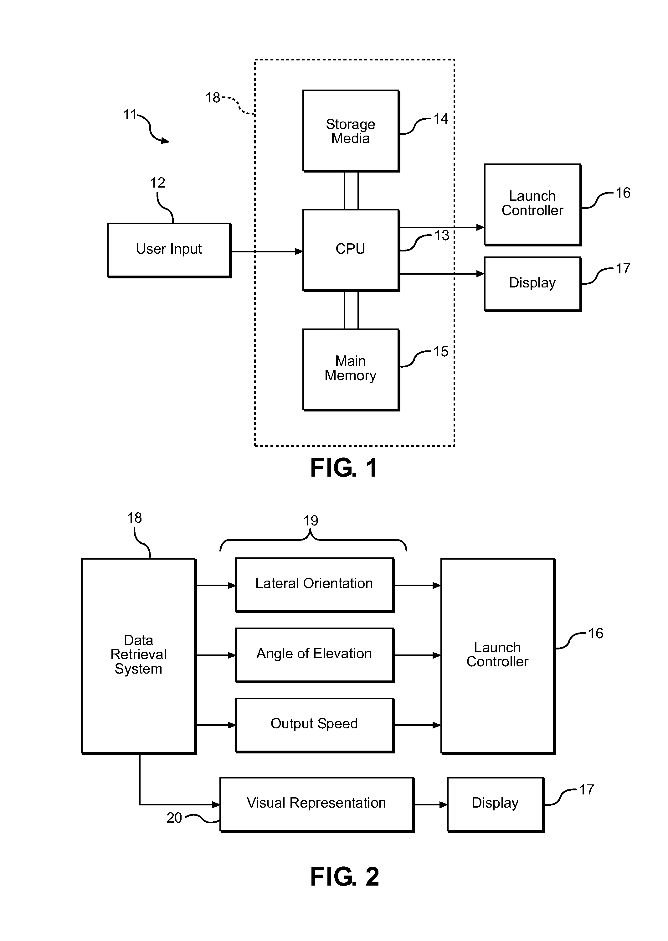
[0033]The football throwing system of the present invention comprises a route input system, a launch controller, and a football throwing device. The route input system receives user input corresponding to a particular route, processes the input, retrieves data regarding the selected route from a storage media, and outputs said data to the display and to the launch controller. The launch controller receives the launch variables from the route input system...


PUM


Abstract

Described is an automated football throwing system and method of operation thereof. The system comprises a route input system, a launch controller, and a football throwing device. In operation, a user inputs the route desired to be executed. The processor accesses a visual illustration of the route from the storage media and displays the visual illustration on a display. Additionally, the data retrieval system accesses data regarding the launch variables which may include the lateral orientation, angle of elevation, and output speed corresponding to a selected route. The launch controller adjusts the football throwing device in accordance with the launch variables for the specific route. The football throwing device comprises a pair of coacting wheels adapted to propel a football and separated by a space in which a football may be inserted. A loading mechanism moves a football received from a storage receptacle into the space between the coacting wheels.

Description

CROSS REFERENCE TO RELATED APPLICATION[0001]This application claims the benefit of U.S. Provisional Application No. 61 / 812,581 filed on Apr. 16, 2013, entitled “Football Quarterback Machine.” The above identified patent application is herein incorporated by reference in its entirety to provide continuity of disclosure.BACKGROUND OF THE INVENTION[0002]1. Field of the Invention[0003]The present invention relates to a football throwing system. More specifically, the present invention relates to a football throwing system comprising a route input system, a launch controller, and a football throwing device. A user can input a specific route, and the processor will retrieve data corresponding to said route from a storage media. The data includes a visual representation of the route which is sent to a display. Additionally, the football throwing device is adjusted by a launch controller in accordance with the launch variables corresponding to the specific route inputted by the user. Once a...

Claims


Application Information

Patent Timeline
IPC IPC(8): A63B69/40
CPCA63B69/406A63B71/0619A63B24/0075A63B2071/0675A63B24/0087A63B2071/065
Inventor DEESE, JULIAN
Owner DEESE JULIAN
Why Eureka
Try Eureka