
Charging system

a charging system and charging terminal technology, applied in the direction of electric vehicles, safety/protection circuits, transportation and packaging, etc., can solve the problems of increasing the likelihood of a terminal contact failure between and the inability to communicate between the battery pack and the charger, so as to reduce the likelihood of a terminal contact failure between the terminals and the number of terminals between the charger and the battery pack

Inactive Publication Date: 2014-10-16
MAKITA CORP
View PDF4 Cites 23 Cited by
  • Summary
  • Abstract
  • Description
  • Claims
  • Application Information

AI Technical Summary

Benefits of technology

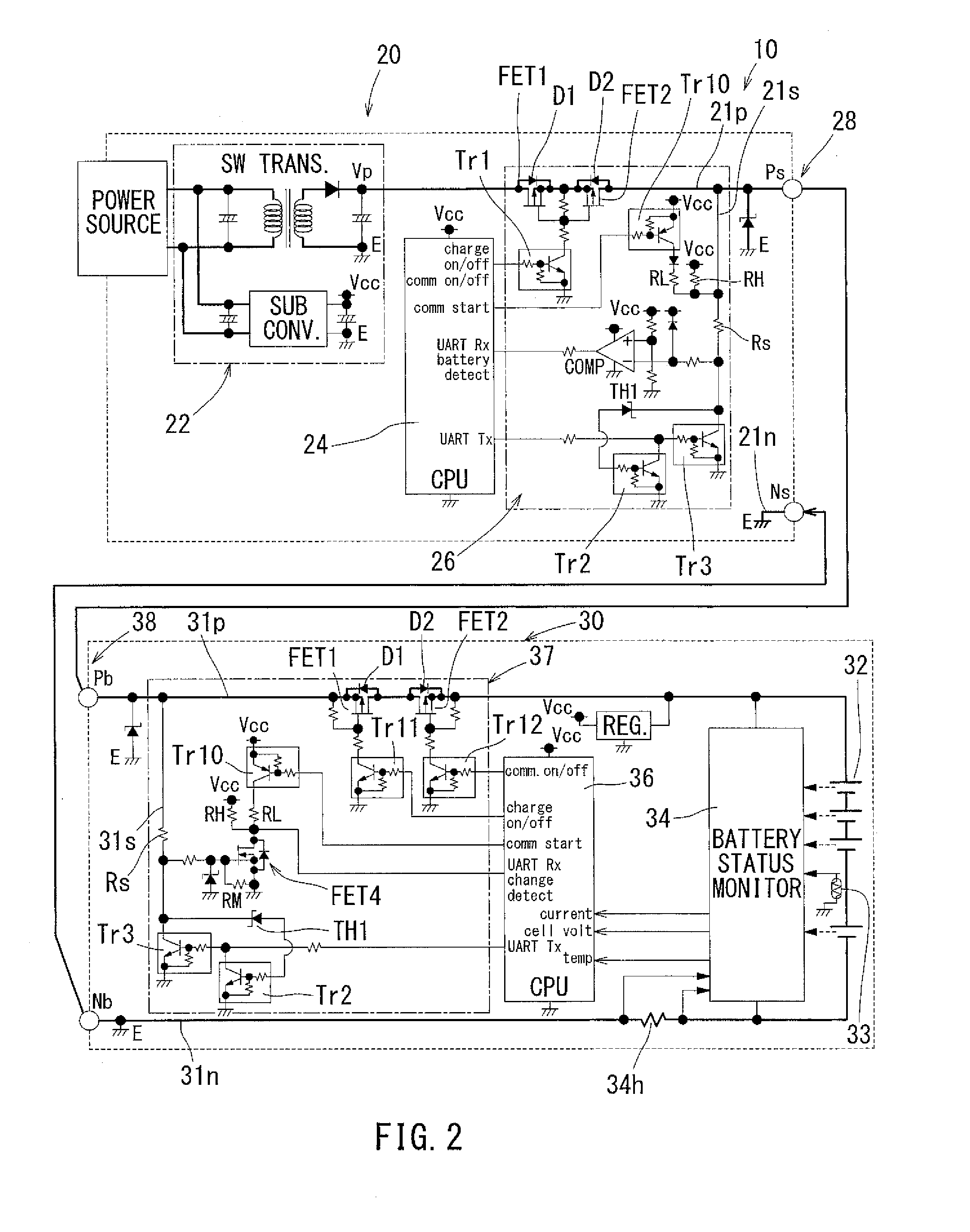
The invention allows for communication between a charger and a battery pack or separate instrument through the same power lines used for charging. This eliminates the need for a dedicated communication terminal, reducing the number of terminals and the likelihood of failure. Additionally, the invention includes an interlock to prevent charging current from flowing into the communication line. This ensures that the battery pack or separate instrument can communicate safely without interference from charging current. Overall, this invention improves communication reliability and safety between the charger and battery pack or separate instrument.

Problems solved by technology

However, when the number of terminals such as the power supply terminal and the communication terminal increases, the likelihood of a terminal contact failure between the charger and the battery pack may increase.
However, in the method in which communication is performed using the inductance component in the cell of the battery pack, communication can be performed only between the battery pack and the charger that have the same inductance component in the cells.
That is, communication cannot be performed between the battery pack and the charger that have different inductance components in the cells.

Method used


Image

  • Charging system
  • Charging system
  • Charging system

Examples


Embodiment Construction

[0039]Each of the additional features and teachings disclosed above and below may be utilized separately or in conjunction with other features and teachings to provide an improved charging system. Representative examples of the present teaching, which examples utilize many of these additional features and teachings both separately and in conjunction with one another, will now be described in detail with reference to the attached drawings. This detailed description is merely intended to teach a person of skill in the art further details for practicing preferred aspects of the present teachings and is not intended to limit the scope of the invention. Only the claims define the scope of the claimed invention. Therefore, combinations of features and steps disclosed in the following detailed description may not be necessary to practice the invention in the broadest sense, and are instead taught merely to particularly describe representative examples of the invention. Moreover, various fe...


PUM


Abstract

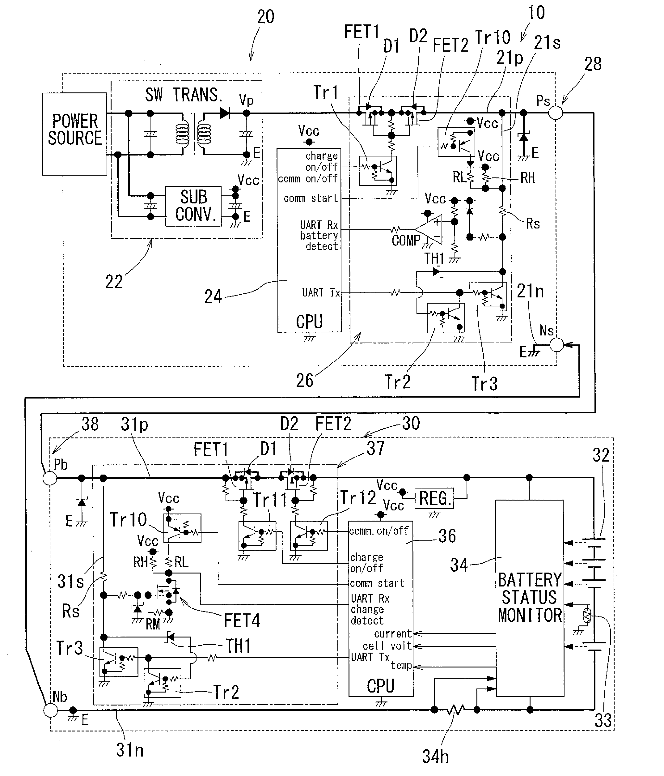
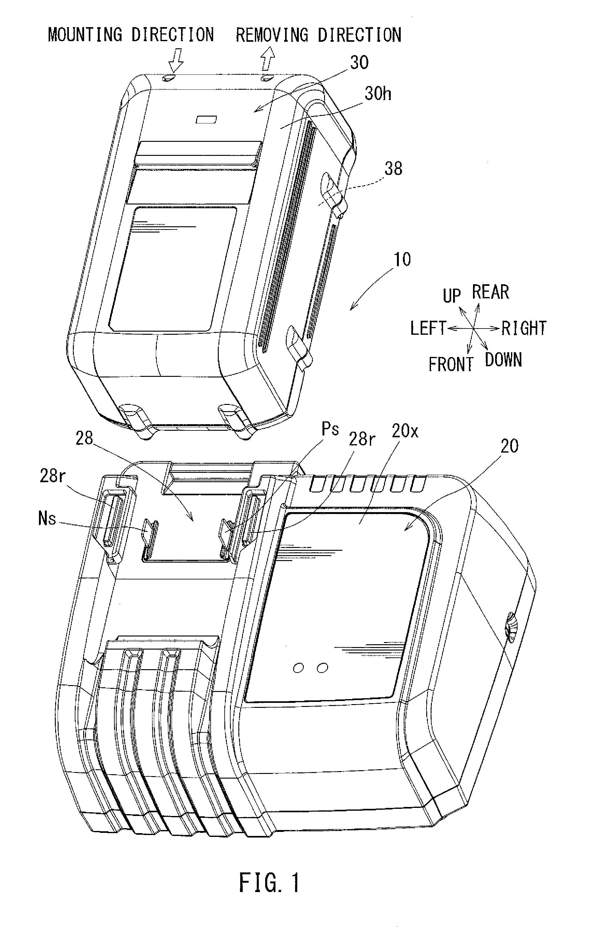
In a charging system in which a charging current flows to a cell via power supply lines in a state where a charger and a battery pack are connected, two FETs for opening and closing a route in each power supply line are provided both at the charger side and the battery pack side. When the charger and the battery pack are connected to each other and FETs at the charger side and FETs at the battery pack side are set to be open, the power supply lines between FETs at the charger side and FETs at the battery pack side can be used as a communication line.

Description

[0001]This application claims priority to Japanese patent application serial number 2013-85607, the contents of which are incorporated herein by reference.BACKGROUND OF THE INVENTION[0002]1. Field of the Invention[0003]The present invention relates to a charging system in which a charger and a battery pack can be connected to each other directly or indirectly via a separate instrument. A charging current can flow to a cell of the battery pack via power supply lines when the charger and the battery pack are connected.[0004]2. Description of the Related Art[0005]Japanese Laid-Open Patent Publication No. 2012-095417 discloses a technology relative to a charger that is used to charge a battery pack serving as a power supply for an electric power tool.[0006]The charger disclosed in Japanese Laid-Open Patent Publication No. 2012-095417 includes a pair of power supply terminals and a plurality of communication terminals. When installing the battery pack onto the charger, power supply termi...

Claims


Application Information

Patent Timeline
Patent Type & Authority Applications(United States)
IPC IPC(8): H02J7/00
CPCH02J7/0045H02J7/0031H02J7/0036H01M10/4257Y02E60/10
Inventor SUZUKI, HITOSHINODA, MASAFUMI
Owner MAKITA CORP
Learn More