Display device

a display device and liquid crystal technology, applied in the direction of instruments, static indicating devices, etc., can solve the problems of deteriorating image quality and delayed convergence of common potentials, and achieve the effects of preventing fluctuation, reducing the number of connection terminals, and preventing image quality from deteriorating

Active Publication Date: 2009-06-11
JAPAN DISPLAY INC
View PDF14 Cites 12 Cited by
  • Summary
  • Abstract
  • Description
  • Claims
  • Application Information

AI Technical Summary

Benefits of technology

[0012]When a drive operation and a timing operation are carried out in the above described configuration, fluctuation can be prevented in the common potential, or the fluctuation can be dispersed, and thus, it can be expected that the image quality can be prevented from deteriorating due to inconsistency in the display brightness, that is to say, lateral smearing.
[0013]In addition, it becomes possible to reduce the number of connection terminals between the liquid crystal panel (time division switch) and the source signal generating circuit through RGB time division drive. As a result, higher precision and higher resolution can be expected in the liquid crystal panel. Furthermore, it becomes possible to increase the yield in manufacture, because the number of connection terminals can be reduced. At the same time, the cost for the liquid crystal display device can be expected to lower when the number of terminals is reduced in the source signal generating circuit.
[0014]In addition, according to the present invention, the type of display signal RGB supplied to the last pixel within each horizontal period is switched frame by frame, and therefore, the fluctuation in the common potential can be dispersed in the direction of time, and thus, it can be expected that the image quality as viewed by the human eye can be prevented from deteriorating due to inconsistency in the display brightness, that is to say, lateral smearing.
[0015]In addition, according to the present invention, the type of display signal RGB supplied to the last pixel within each horizontal period is switched pixel by pixel, and therefore, the fluctuation in the common potential can be set off within the same space, and thus, the fluctuation in the common potential can be reduced, and it can be expected that the image quality can be prevented from deteriorating due to inconsistency in the display brightness, that is to say, lateral smearing.

Problems solved by technology

Here, in conventional line sequence driving systems, only the time for starting one horizontal period fluctuates, while in RGB time division drive, the potential of the drain line fluctuates in accordance with the timing with which R, G and B data is written in, as described above, and therefore, the convergence of the common potential is delayed, and the image quality deteriorates, due to the display brightness being different from the desired display brightness.

Method used


Image

  • Display device
  • Display device
  • Display device

Examples


first embodiment

[0030]In the following, the present invention is described in reference to FIGS. 1 to 10.

[0031]First, the configuration of the liquid crystal display device according to the first embodiment of the present invention is described in reference to FIGS. 1 and 2, citing RGB time division drive as one example.

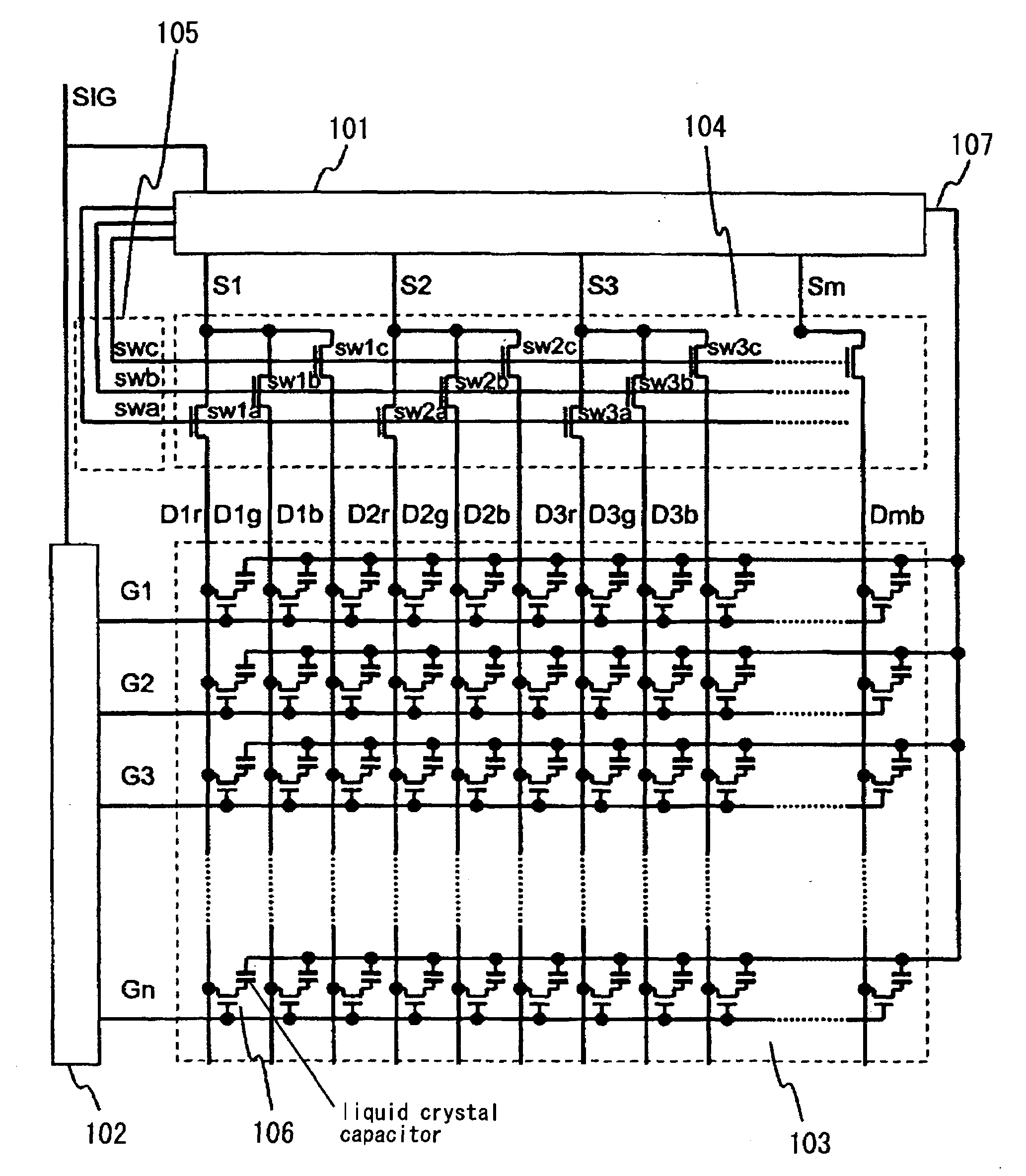
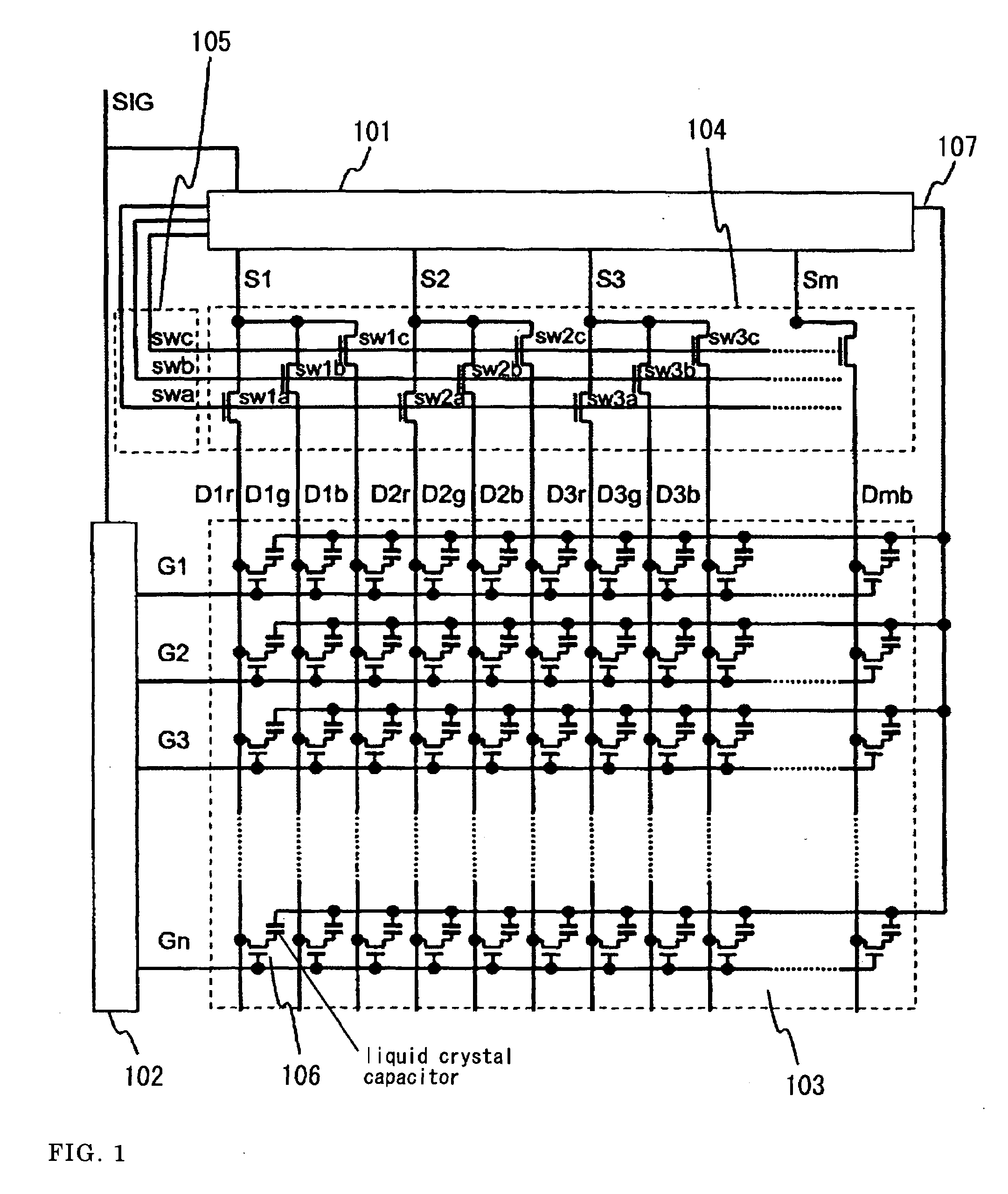
[0032]FIG. 1 is a diagram showing the configuration of the liquid crystal display device according to the first embodiment of the present invention. In FIG. 1, 101 is a source signal generating circuit, and the source signal generating circuit outputs a group of display signal lines (S1, S2, S3 . . . ) for transmitting a display signal (a positive [high-potential] signal or a negative [low potential] signal relative to the potential of the counter electrode) to a liquid crystal panel 103. Here, the source signal generating circuit 101 outputs display signals of the same polarity from even and odd terminal to the group of display signal lines. The group of display signal lines is con...

second embodiment

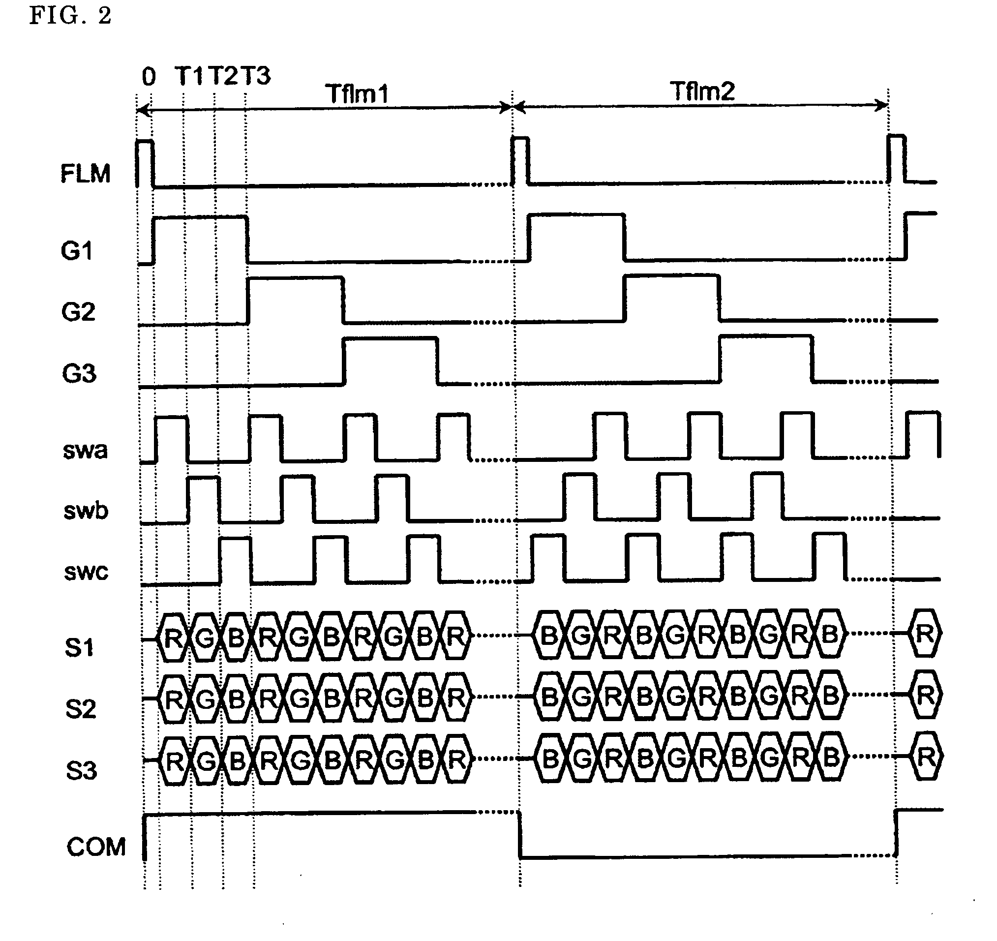
[0057]In the present invention, as shown in the control signal waveform in FIG. 12, during the vertical period for carrying out an operation for the writing in of a display signal with the negative polarity (Tflm1), swa within the time division switch controlling signal is at a HIGH potential and swb and swc are at a LOW potential during the first selection period, that is to say, from time 0 to time T1, swb within the time division switch controlling signal is at a HIGH potential and swa and swc are at a LOW potential during the second selection period, that is to say, from time T to time T2, and swc within the time division switch controlling signal is at a HIGH potential and swa and swb are at a LOW potential during the third selection period, that is to say, from time T2 to time T3. Here, during the first selection period, as described in reference to FIG. 11, the group of display signal lines S1, S4, S7 . . . for connecting the time division switch control signal swa to the dra...


PUM


Abstract

In RGB time division drives, there is capacitor coupling due to the effects of fluctuation in the drain lines, and thus, the image quality deteriorates (lateral smearing), so that the display brightness becomes different from the desired display brightness due to delay in the convergence of the fluctuation of the common potential, and thus, it is a goal to prevent the image quality from deteriorating (lateral smearing).
In RGB time division drives, the order of time division is switched for each frame, or in the direction of the horizontal lines.

Description

BACKGROUND OF THE INVENTION[0001]The present invention relates to a liquid crystal display device, and in particular, to a drive system and a drive circuit for a liquid crystal display in accordance with a time division system in which a source signal generating circuit is mounted.[0002]The mobility of poly-Si (polysilicon) under electrical field effects is greater than the mobility of amorphous Si under electrical field effects, which is approximately 0.5 to 1 cm2 / Vs, by approximately several tens to 200 cm2 / Vs. Therefore, peripheral circuits, such as signal circuits and scanning circuits, can be formed on the same substrate as the liquid crystal display portion using poly-Si TFT's. In addition, periphery circuits and a liquid crystal display portion can be formed on the same substrate using poly-Si TFT's, and thus, connection with external peripheral circuits, such as source signal generating circuits, becomes unnecessary, and it becomes possible to implement a liquid crystal disp...

Claims


Application Information

Patent Timeline
Patent Type & Authority Applications(United States)
IPC IPC(8): G09G3/36
CPCG09G3/3614G09G3/3648G09G2320/0257G09G2320/0233G09G2310/08
Inventor TAKADA, NAOKIKUDO, YASUYUKIMAMBA, NORIOERIGUCHI, TAKUYAFURUHASHI, TSUTOMUIWASAKI, SHINICHI
Owner JAPAN DISPLAY INC
Why Eureka
Try Eureka