
Auto focus method and auto focus apparatus

a technology of auto focus and autofocus apparatus, which is applied in the direction of electrical apparatus, steroscopic systems,pictoral communication, etc., can solve the problems of inability to precisely determine the position of each point in the image, the lens may be moved too much, and the stability of the image is destroyed, so as to achieve optimal image stability and fast focusing speed

Inactive Publication Date: 2014-10-16
ALTEK SEMICON
View PDF4 Cites 15 Cited by
  • Summary
  • Abstract
  • Description
  • Claims
  • Application Information

AI Technical Summary

Benefits of technology

The present invention provides an auto focus method and apparatus that offer faster focusing speed and optimal image stability. It uses a 3D depth map generated through a stereoscopic image processing technique and performs an optimization process on the map to obtain a focusing position. This allows for an AF action to be performed within a single image shooting period. The method and apparatus do not require searching for the maximum focus value, which prevents breathing and improves image stability.

Problems solved by technology

Thus, it is very time-consuming.
Besides, when a digital camera moves its lens, the lens may be moved too much therefore has to be moved back and forth.
The phenomenon of breathing refers to the change of angle of view of a lens when shifting the focus and therefore destroys the stability of the image.
However, generally speaking, when 3D coordinate position information of each pixel in an image is obtained through image processing of the present stereoscopic vision technique, the position of each point in the image cannot be determined precisely.
Since it is difficult to identify relative depth or precisely determine depth information of each point in a texture-less or flat area, “holes” may be produced in the 3D depth map.
As a result, precise positioning may become even more difficult and more holes may be produced in the 3D depth map.
Moreover, the execution of subsequent image focusing procedures may be affected.

Method used


Image

  • Auto focus method and auto focus apparatus
  • Auto focus method and auto focus apparatus
  • Auto focus method and auto focus apparatus

Examples


Embodiment Construction

[0030]Reference will now be made in detail to the present preferred embodiments of the invention, examples of which are illustrated in the accompanying drawings.

[0031]Wherever possible, the same reference numbers are used in the drawings and the description to refer to the same or like parts.

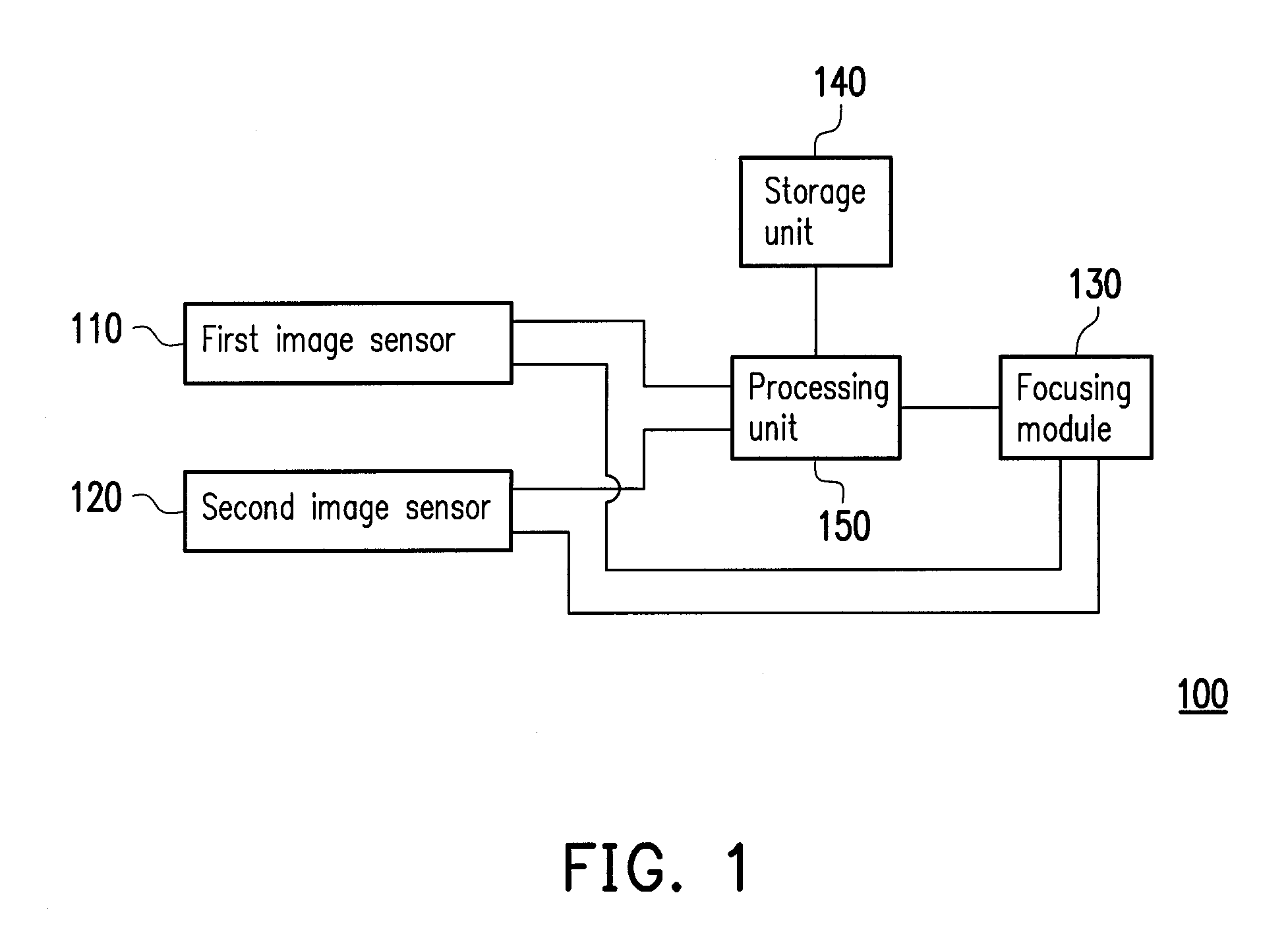
[0032]FIG. 1 is a block diagram of an auto focus (AF) apparatus according to an embodiment of the present invention. Referring to FIG. 1, the AF apparatus 100 in the present embodiment includes a first image sensor 110, a second image sensor 120, a focusing module 130, a storage unit 140, and a processing unit 150. In the present embodiment, the AF apparatus 100 is a digital camera, a digital video camcorder (DVC), or any other handheld electronic apparatus which can be used for capturing videos or photos. However, the type of the AF apparatus 100 is not limited in the present invention.

[0033]Referring to FIG. 1, in the present embodiment, the first image sensor 110 and the second image sensor 1...


PUM


Abstract

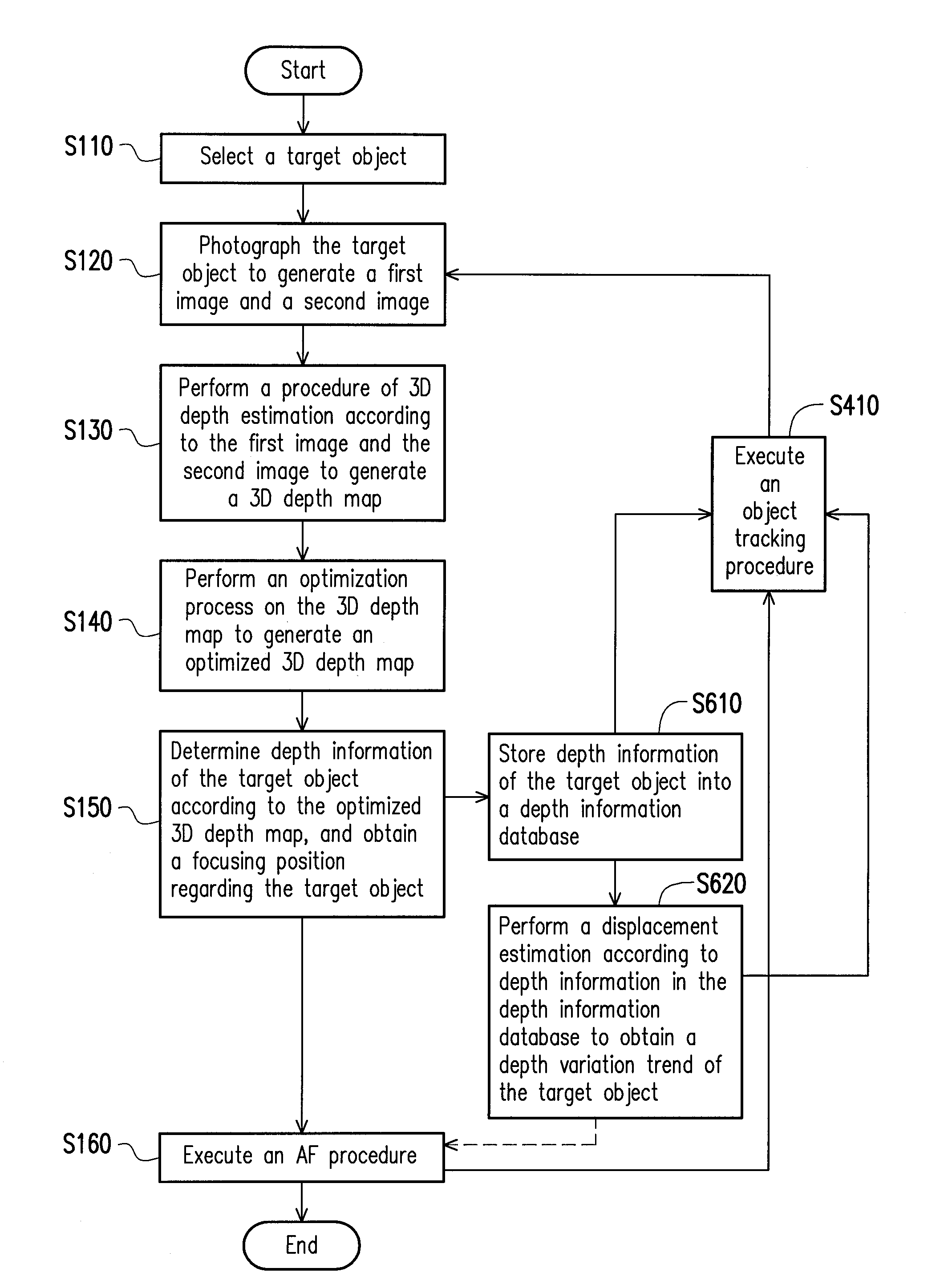
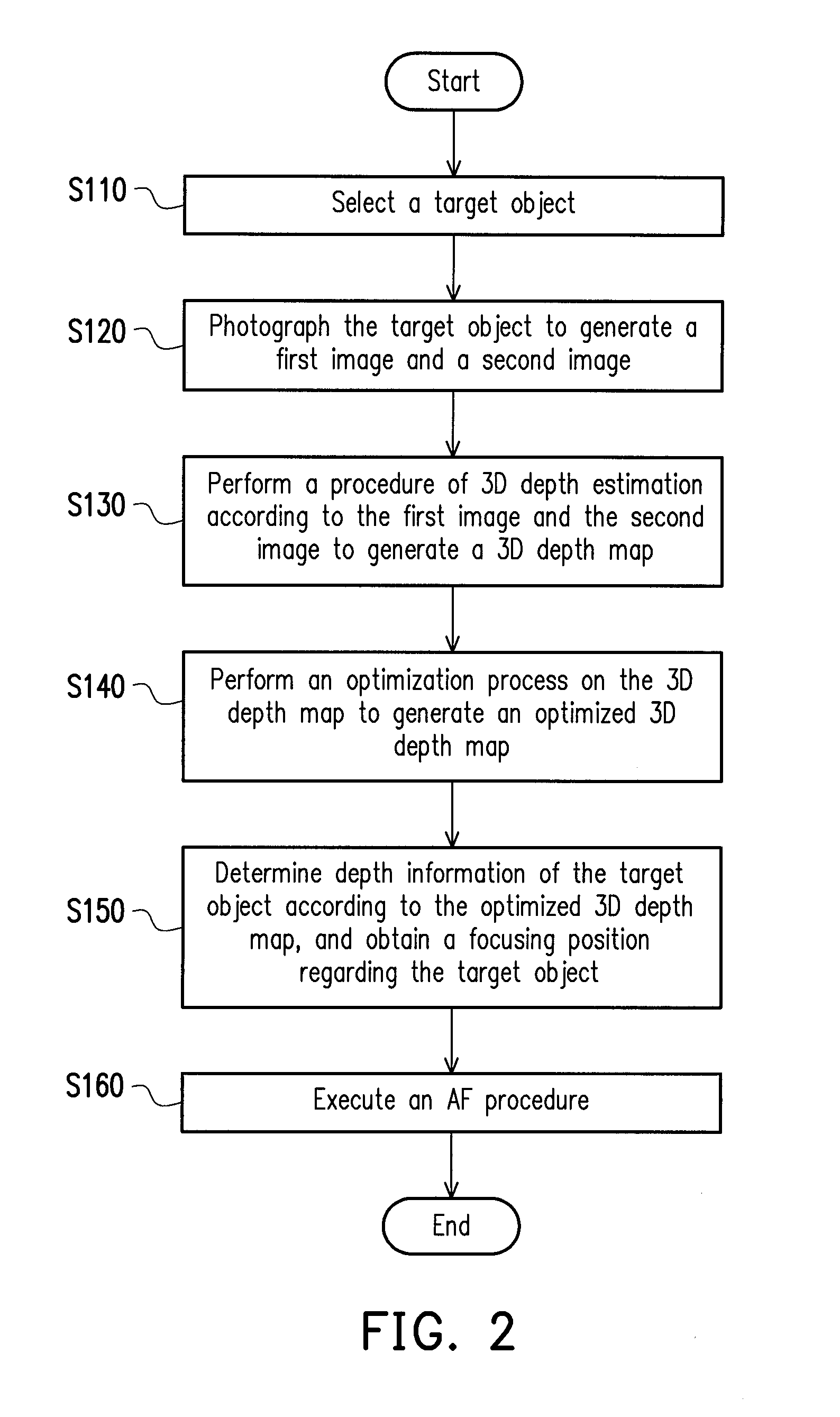
An auto focus (AF) method adapted to an AF apparatus is provided. The AF method includes following steps. A target object is selected and photographed by a first image sensor and a second image sensor to generate a first image and a second image. A procedure of three-dimensional (3D) depth estimation is performed according to the first image and the second image to generate a 3D depth map. An optimization process is performed on the 3D depth map to generate an optimized 3D depth map. A piece of depth information corresponding to the target object is determined according to the optimized 3D depth map, and a focusing position regarding the target object is obtained according to the pieces of depth information. The AF apparatus is driven to execute an AF procedure according to the focusing position. Additionally, an AF apparatus is provided.

Description

CROSS-REFERENCE TO RELATED APPLICATION[0001]This application claims the priority benefit of Taiwan application serial no. 102112875, filed on Apr. 11, 2013. The entirety of the above-mentioned patent application is hereby incorporated by reference herein and made a part of this specification.BACKGROUND OF THE INVENTION[0002]1. Field of the Invention[0003]The present invention generally relates to an auto focus (AF) technique, and more particularly, to an AF method and an AF apparatus adopting a stereoscopic image processing technique.[0004]2. Description of Related Art[0005]A digital camera usually has a very complicated mechanical structure and enhanced functionality and operability. Besides the user's photographing skill and the surrounding environment, the auto focus (AF) system in a digital camera also has a great impact on the quality of images captured by the digital camera.[0006]Generally, an AF technique refers to that a digital camera moves its lens to change the distance b...

Claims


Application Information

Patent Timeline
Patent Type & Authority Applications(United States)
IPC IPC(8): H04N13/02H04N13/239
CPCH04N13/0271H04N2013/0081H04N13/239H04N13/271H04N23/67
Inventor CHANG, WEN-YANHUANG, YU-CHENCHOU, HONG-LONGKANG, CHUNG-CHIA
Owner ALTEK SEMICON
Learn More