Reflective diffusion lens and lighting installation

Inactive Publication Date: 2014-10-16
SAMSUNG ELECTRONICS CO LTD
View PDF12 Cites 10 Cited by
  • Summary
  • Abstract
  • Description
  • Claims
  • Application Information

AI Technical Summary

Benefits of technology

[0011]In an aspect of one or more embodiments, there is provided an optical device including a reflective diffusion lens tha

Problems solved by technology

However, as the size of the light guide plate increases, the yield rate may decreas

Method used


Image

  • Reflective diffusion lens and lighting installation
  • Reflective diffusion lens and lighting installation
  • Reflective diffusion lens and lighting installation

Examples


Example

[0044]Reference will now be made in detail to embodiments, examples of which are illustrated in the accompanying drawings, wherein like reference numerals refer to like elements throughout.

[0045]An embodiment of a reflective diffusion lens 100 and a lighting installation 500 including the reflective diffusion lens 100 will be described in detail with reference to the accompanying drawings.

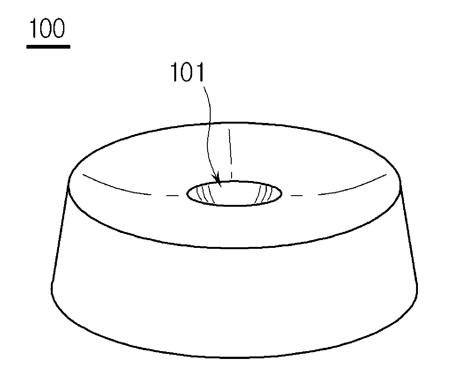
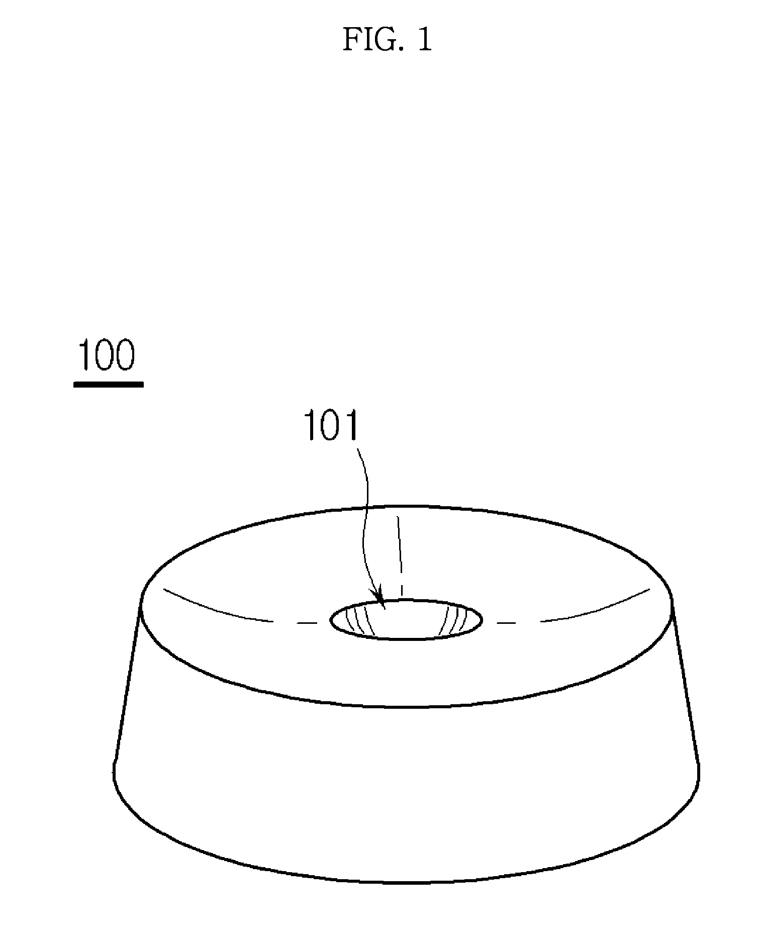
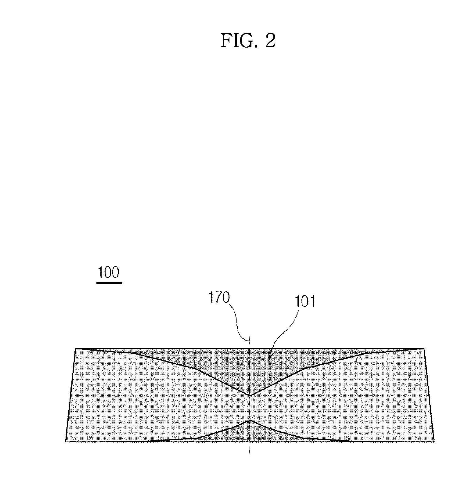
[0046]FIG. 1 is a perspective view illustrating the reflective diffusion lens 100, and FIG. 2 is a longitudinal cross-sectional view illustrating the reflective diffusion lens 100.

[0047]As shown in FIGS. 1 and 2, the reflective diffusion lens 100 has a shape of a circular truncated cone, and a groove 101 is formed at the center of a reflective surface 110 and a bottom surface 130. In addition, the longitudinal cross section of the reflective diffusion lens 100 has a trapezoidal shape. In FIG. 2, the left portion and the right portion of the lens are symmetrically arranged around the central axis of...


PUM


Abstract

A reflective diffusion lens may include a bottom surface concave toward a reflective surface, a longitudinal cross section of the bottom surface being formed in a parabolic shape or normal distribution shape such that light incident upon the bottom surface is incident upon the reflective surface, and the reflective surface concave toward the bottom surface. The reflective surface may include a concave surface having a longitudinal cross section formed in a parabolic shape or normal distribution shape to totally reflect the light transmitted from the bottom surface and incident upon the reflective surface. A lighting installation may include at least one light source to emit light, a reflective diffusion lens to collect light emitted from the light source, and a reflective plate positioned at a lower portion of the light source and adapted to adjust a direction or amount of light reaching the reflective plate.

Description

CROSS-REFERENCE TO RELATED APPLICATIONS[0001]This application claims the priority benefit of Korean Patent Application No. 10-2013-0039404, filed on Apr. 10, 2013 in the Korean Intellectual Property Office, the disclosure of which is incorporated herein by reference.BACKGROUND[0002]1. Field[0003]Embodiments relate to a reflective diffusion lens for a direct type lighting installation.[0004]2. Description of the Related Art[0005]Backlight units (BLUs), which are used in liquid crystal displays (LCDs), include light-guide-plate type BLUs and direct type BLUs.[0006]A light guide plate is a component to adjust luminance of a BLU and perform uniform lighting. The light guide plate is a plastic lens functioning to uniformly deliver light emitted from a cold-cathode fluorescent lamp (CCFL) to the entire surface of an LCD.[0007]In the case of the light-guide-plate type lighting installation, it may be possible to manufacture a surface light source having an area equal to or greater than 1 m...

Claims


Application Information

Patent Timeline
IPC IPC(8): F21V13/04F21V7/04
CPCF21V7/04F21V13/04G02B19/0028G02B19/0061G02F1/133603G02F1/133607G02B5/0205
Inventor KIM, CHEOUL YOUNGLEE, KEUN BUMLEE, SEUNG JAEKIM, SUN GILKIM, CHANG JULEE, GEUN HOJANG, DONG SEOB
Owner SAMSUNG ELECTRONICS CO LTD
Why Eureka
Try Eureka