Surgical clip appliers

a surgical and clip technology, applied in the field of surgical instruments, can solve the problems of trauma to patients, body tissue damage, and the jaw members of the surgical clip applier may unintentionally grasp body tissue at the surgical site,

Active Publication Date: 2014-10-23
TYCO HEALTHCARE GRP LP
View PDF8 Cites 72 Cited by
  • Summary
  • Abstract
  • Description
  • Claims
  • Application Information

AI Technical Summary

Benefits of technology

[0012]In embodiments, the clip follower may include a window formed in a body portion thereof. Upon the at least one handle being further actuated, the distal end of the pusher tip is disposed within the window of the clip follower. The clip follower may be disposed within a distal end of clip channel and a down force of at least one resilient tang of the clip carrier facilitates retaining the clip follower at the distal end of the clip channel.

Problems solved by technology

However, in certain situations, when the same surgical clip applier is mistakenly used after the last clip has been applied, the jaw members of the surgical clip applier may unwantedly grasp body tissue at the surgical site.
As a result, the body tissue may be damaged, which sometimes causes trauma to the patient.

Method used


Image

  • Surgical clip appliers
  • Surgical clip appliers
  • Surgical clip appliers

Examples


Embodiment Construction

[0045]Embodiments of surgical clip appliers in accordance with the present disclosure will now be described in detail with reference to the drawing figures wherein like reference numerals identify similar or identical structural elements. As shown in the drawings and described throughout the following description, as is traditional when referring to relative positioning on a surgical instrument, the term “proximal” refers to the end of the apparatus which is closer to the user and the term “distal” refers to the end of the apparatus which is further away from the user.

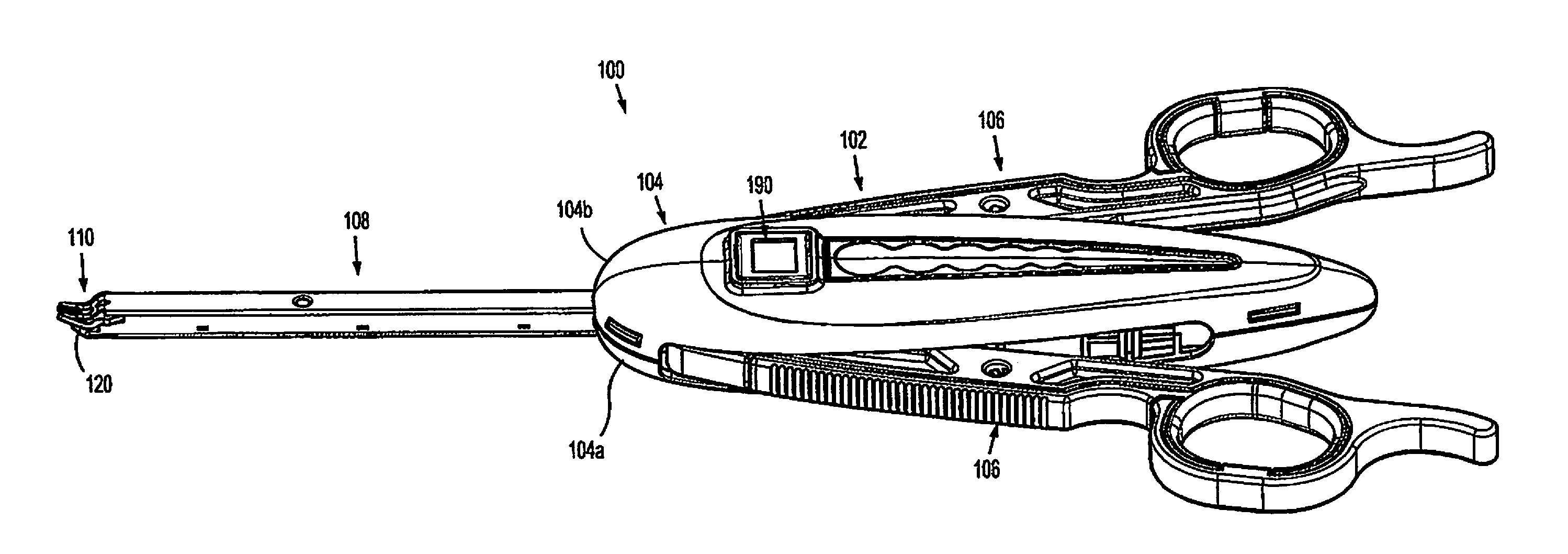
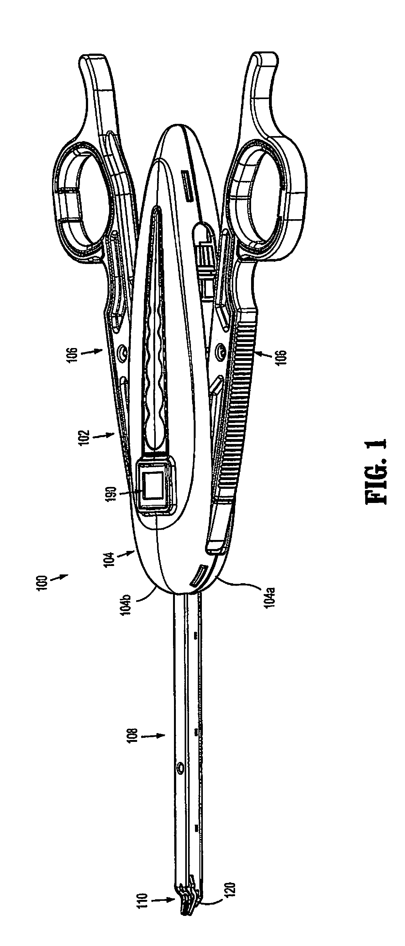
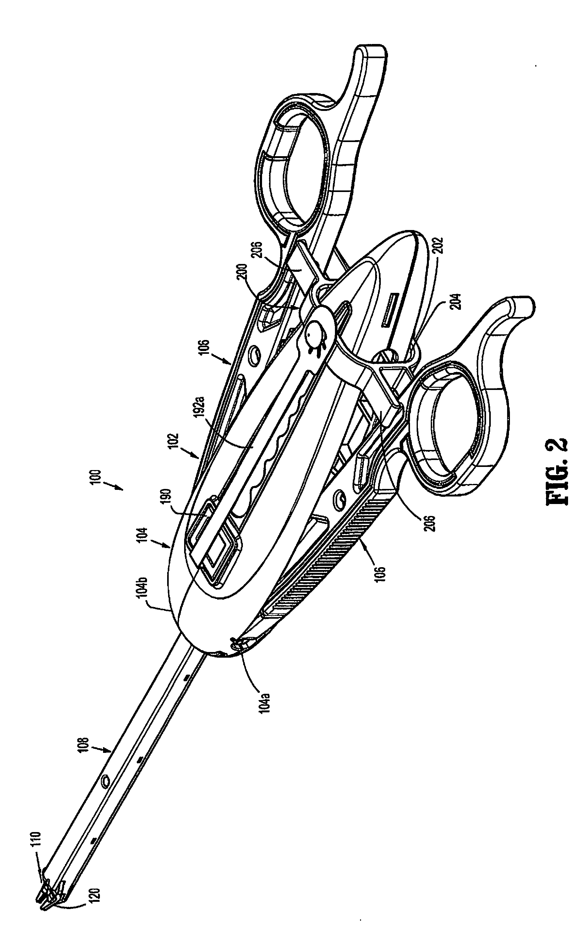
[0046]FIGS. 1-5 illustrate a surgical clip applier in accordance with an embodiment of the present disclosure and is generally designated as 100. Reference may be made to U.S. Pat. No. 8,465,502, filed on Aug. 13, 2009, entitled “Surgical Clip Applier” and U.S. Pat. No. 8,056,565, filed on Aug. 11, 2009, entitled “Surgical Clip Applier and Method of Assembly,” the entire contents of each of which being incorporated her...


PUM


Abstract

A surgical clip applier includes a housing, at least one handle, a channel assembly, a clip carrier, a wedge plate, a clip pusher bar, and a clip follower. The at least one handle is pivotably connected to the housing. The channel assembly extends distally from the housing. The clip carrier is disposed within the channel assembly and defines a channel and a plurality of windows. The wedge plate is reciprocally disposed within the channel assembly. The clip pusher bar is reciprocally positioned within the housing and the channel assembly. The clip follower is slidably disposed within the channel of the clip carrier and disposed proximally of a plurality of clips. The clip follower is configured and dimensioned to lockout the clip applier after a last clip of the plurality of clips has been expelled by the surgical clip applier.

Description

CROSS REFERENCE TO RELATED APPLICATIONS[0001]The present application is a Continuation Application claiming the benefit of and priority to U.S. patent application Ser. No. 12 / 976,120, filed on Dec. 22, 2010, which claims the benefit of and priority to U.S. Provisional Patent Application Ser. No. 61 / 306,174, filed on Feb. 19, 2010, the entire contents of each of which are incorporated herein by reference.[0002]The present application is also a Continuation-in-Part Application claiming the benefit of and priority to U.S. patent application Ser. No. 13 / 890,580, filed on May 9, 2013, which is a Divisional Application claiming the benefit of and priority to U.S. patent application Ser. No. 12 / 540,475, filed on Aug. 13, 2009 (now U.S. Pat. No. 8,465,502), which claims the benefit of and priority to U.S. Provisional Patent Application Ser. No. 61 / 091,467, filed on Aug. 25, 2008, the entire contents of each of which are incorporated herein by reference.BACKGROUND[0003]1. Technical Field[000...

Claims


Application Information

Patent Timeline
Patent Type & Authority Applications(United States)
IPC IPC(8): A61B17/128
CPCA61B2017/2923A61B17/1285A61B17/10A61B2017/12004A61B2017/00115A61B2090/038A61B90/92A61B2090/0803A61B2090/0811A61B2090/0814A61B2017/00407A61B17/128A61B17/12
Inventor ZERGIEBEL, EARL M.CABRERA, RAMIRO
Owner TYCO HEALTHCARE GRP LP
Why Eureka
Try Eureka