Optical collimator for LED lights

Active Publication Date: 2014-10-23
KONINKLIJKE PHILIPS ELECTRONICS NV
View PDF15 Cites 44 Cited by
  • Summary
  • Abstract
  • Description
  • Claims
  • Application Information

AI Technical Summary

Benefits of technology

[0005]It is an object of the present invention to overcome or at least mitigate the problems discussed above, and to provide a collimating optics and a luminaire having an improved CBCP

Problems solved by technology

However, this is not the case if Fresnel lenses are used sinc

Method used


Image

  • Optical collimator for LED lights
  • Optical collimator for LED lights
  • Optical collimator for LED lights

Examples


Example

[0030]As illustrated in the figures, the sizes of layers and regions are exaggerated for illustrative purposes and, thus, are provided to illustrate the general structures of embodiments of the present invention. Like reference numerals refer to like elements throughout.

DETAILED DESCRIPTION OF THE EMBODIMENTS

[0031]The present invention will now be described more fully hereinafter with reference to the accompanying drawings, in which currently preferred embodiments of the invention are shown. This invention may, however, be embodied in many different forms and should not be construed as limited to the embodiments set forth herein; rather, these embodiments are provided for thoroughness and completeness, and fully convey the scope of the invention to the skilled person.

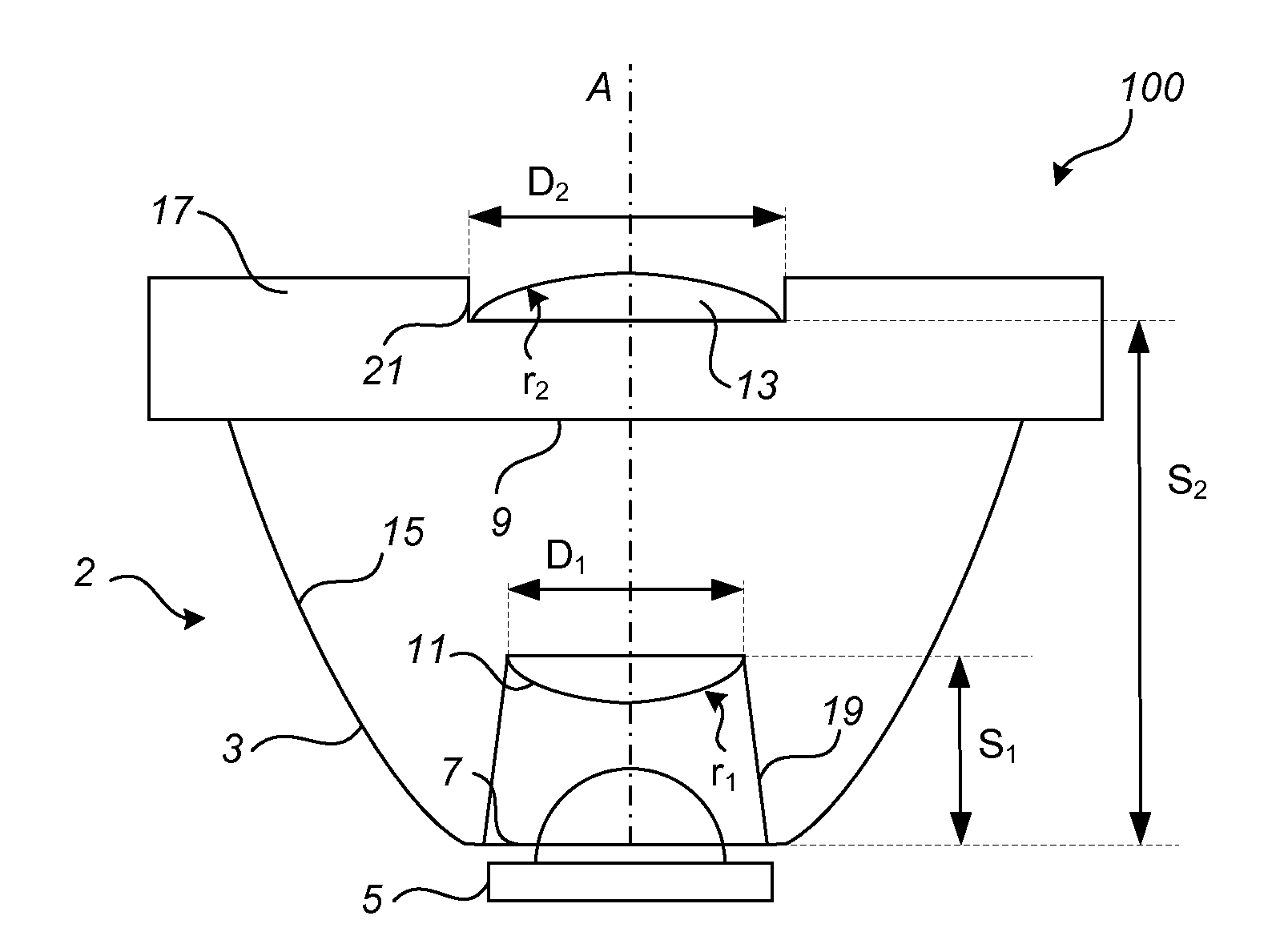
[0032]FIG. 1 illustrates a luminaire 100 comprising a collimating optics 2 and a LED light 5. The collimating optics 2 comprises a reflection collimator 3 such as a total internal reflection collimator. The reflection c...


PUM


Abstract

There is provided a luminaire (1) and a collimating optics (2) for LED lights (5). The collimating optics (2) comprises a reflection collimator (3) having a first aperture (7) for allowing incoming light from a LED light (5) to enter the collimator (3) and a second aperture (9) for allowing outgoing light to exit the collimator (3). The reflection collimator (3) further has a wall (15) with a reflective inner surface for guiding the incoming light from the first aperture (7) towards the second aperture (9). A first convex lens (11) is arranged at a distance from the first aperture (7) for refracting the incoming light, and a second convex lens (13) is arranged at the second aperture (9) for refracting and collimating the outgoing light. With the disclosed collimating optics the collimating capability is improved without the size of the optics being increased.

Description

FIELD OF THE INVENTION[0001]The present invention generally relates to the field of collimation of light. In particular, it relates to a collimating optics for light emitting diode (LED) lights.BACKGROUND OF THE INVENTION[0002]Replacement of halogen spotlighting lamps by LEDs is a growing market. Replacing halogen lamps by LEDs is quite challenging since halogen lamps and LEDs have different properties. More specifically, a difference between halogen lamps and LEDs is that LEDs have a limited flux output in comparison to halogen lamps. In order for a LED spotlight to have the same maximum intensity at specific beam angles as a halogen spotlight, the optics of the LED spotlight therefore needs to provide a much higher intensity in the center of the beam per unit flux in order to compensate for the limited flux output. The intensity in the center of the beam per unit flux is often referred to as center beam candle power (CBCP) per lumen value, or simply Cd / lm or CBCP / lm.[0003]In view ...

Claims


Application Information

Patent Timeline
IPC IPC(8): G02B17/08F21K99/00G01B21/20
CPCG02B17/08F21K9/30G01B21/20G02B19/0066G02B19/0028F21V5/045F21V7/0091F21K9/20F21Y2115/10F21Y2105/10F21V13/04G02B17/0868G02B19/0061G02B27/0916
Inventor SUN, LI WEILI, YUNSUN, YAN MENGCHENG, LI
Owner KONINKLIJKE PHILIPS ELECTRONICS NV
Why Eureka
Try Eureka