
Cuff Brace

a brace and cuff technology, applied in the field of cuff brace, can solve the problems of unfinished, non-uniform, sloppy end,

Inactive Publication Date: 2014-10-30
PERRO SHEDRICK ROYALE
View PDF39 Cites 0 Cited by
  • Summary
  • Abstract
  • Description
  • Claims
  • Application Information

AI Technical Summary

Benefits of technology

The present invention is a Cuff Brace that joins two studs to a center frame to secure the cuffs together at the buttonholes and edge of the cuff. It also adds an attractive lining to the cuff using the frame. This creates a more complete look to the edge of the cuff.

Problems solved by technology

When the cuffs are joined together, it leaves the edge of the cuffs undefined, leaving an unfinished, non uniformed and sloppy end result.

Method used


Image

  • Cuff Brace
  • Cuff Brace
  • Cuff Brace

Examples


Embodiment Construction

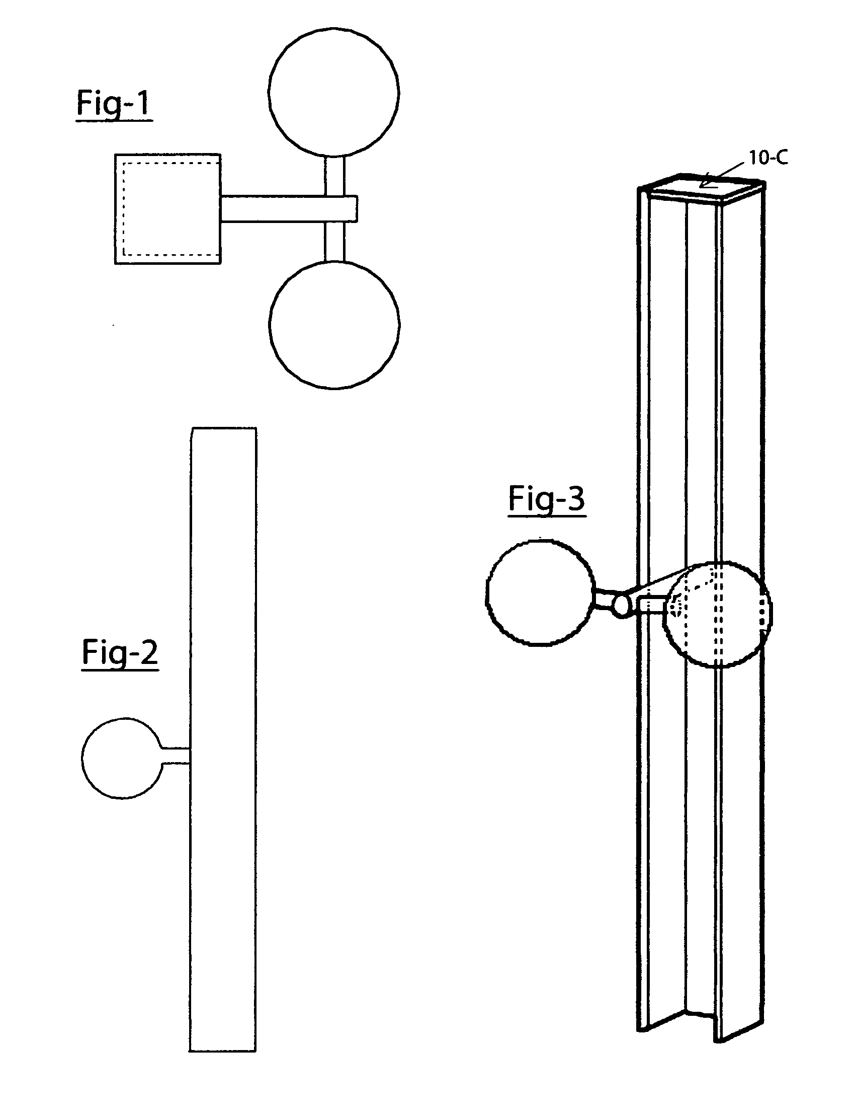
[0016]Referring to the invention in more detail, in FIG. 1 to FIG. 3, there is shown a top, side and perspective view of one preferred embodiment of the cuff brace invention.

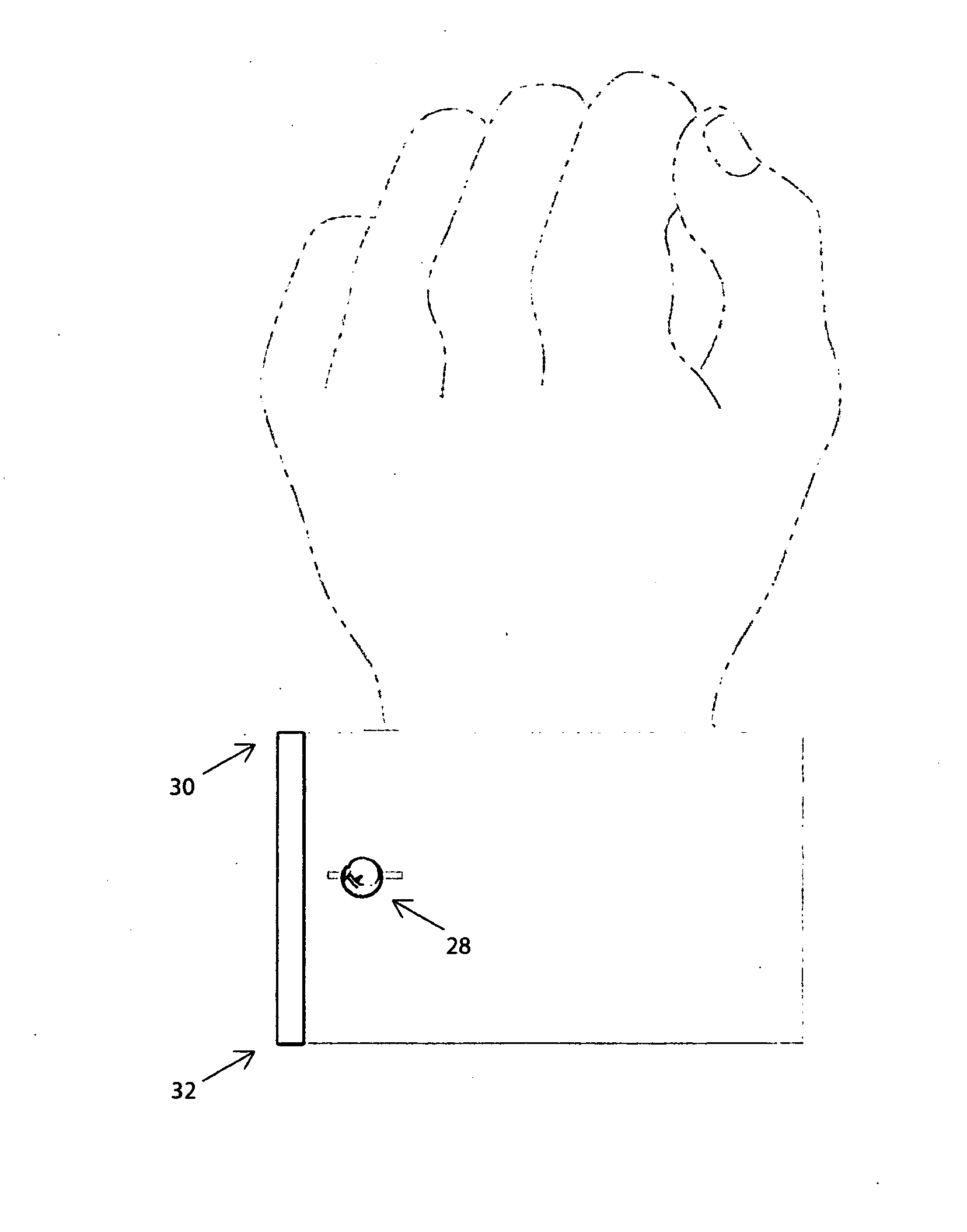
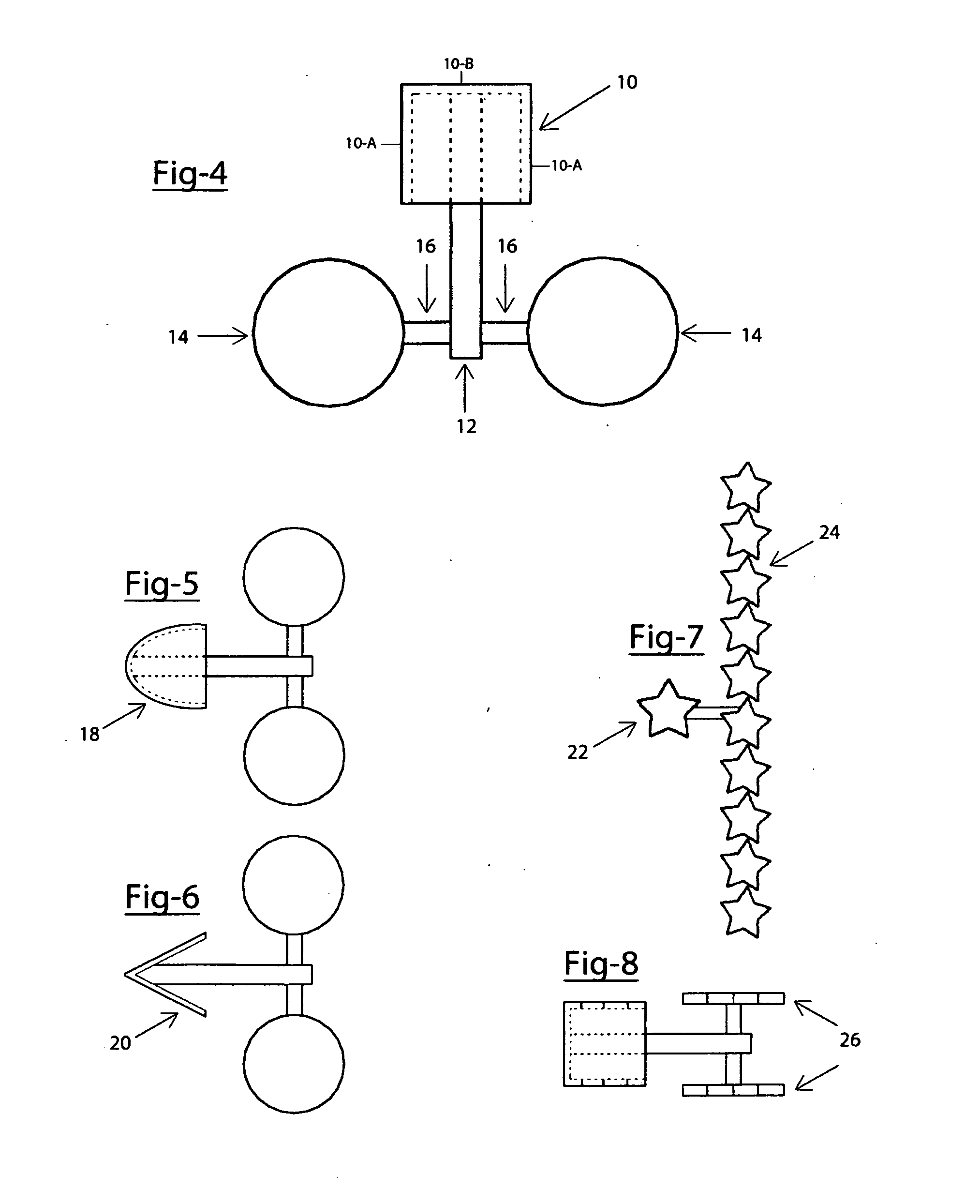
[0017]FIG. 4 is a top view of the cuff brace, showing the components of the invention. The Cuff Brace is comprised of four parts. One Frame 10; One Center Pin 12; Two Studs 14; and two cross pins 16. The frame 10 on this preferred embodiment is a U-Shaped piece with two sides 10-A, a front 10-B, and a top 10-C. The center pin 12 in this preferred embodiment is a cylinder that is attached to the frame 10. The studs 14, on this preferred embodiment are spheres that are attached to the cross pins 16. The cross pins 16 are attached to the center pin 12 to form a T-Bar.

[0018]FIG. 5 is a top view of the invention showing an alternative embodiment to the frame of the invention, which is an open ended oval 18 and FIG. 6 which is a top view of the invention showing an alternative embodiment to the frame of the invention ...


PUM


Abstract

My invention is a Cuff Brace for use with a shirt or blouse having French Cuff sleeves, to fasten the cuffs together and to create a decorative edge at the end of the cuffs. The Cuff Brace connects the French Cuffs together by two studs being inserted into the eyelets or buttonholes of the french cuff and the edge of the french cuff being tucked inside the Frame of the Cuff Brace. The Cuff Brace can be made from materials such as, but not limited to, platinum, gold, silver, steel, titanium, or relatively any of the precious metals. The Cuff Brace can also be made of wood or plastic. The Cuff Brace can also have ornamental designs that include precious and semiprecious stones. The Frame, Pins and Studs of the present invention can be constructed in a variety of embodiments, while maintaining the overall function of the present invention.

Description

[0001]This invention is used as a high luxury accessory to secure and fashion French Cuffs on the sleeves of any ordinary French Cuff shirt. It is furthermore used as a new method and alternative to using cuff links to secure french cuffs. It not only secures the french cuff at the eyeholes, but it also provides a decorative trim around the edge of the French Cuff.[0002]The present invention consists in the combination and arrangement of parts, as will be hereinafter fully described, shown in the accompanying drawings, and particularly pointed in the appended claims, it being understood that changes in the form, proportion, size and minor details may be made within the scope of the claims without departing from the spirit or sacrificing any of the advantages of the invention.[0003]In the drawings FIG. 1 is top view of the cuff brace; FIG. 2 is a side view of the cuff brace; FIG. 3. is a perspective view of the cuff brace; FIG. 4 is a top view, illustrating the parts of the cuff brac...

Claims


Application Information

Patent Timeline
IPC IPC(8): A44B5/02
CPCA44B5/02Y10T24/3643A44B5/00
Inventor PERRO, SHEDRICK, ROYALE
Owner PERRO SHEDRICK ROYALE
Learn More