Vehicle fuel tank arrangement and method for managing the supply of fuel to a vehicle

a technology for fuel tanks and vehicles, applied in the direction of liquid fuel feeders, machines/engines, transportation items, etc., can solve the problems of not being fully satisfactory to drivers, not being practicable, and always being possible, so as to increase vehicle autonomy and minimize the period of time

Inactive Publication Date: 2014-10-30
VOLVO LASTVAGNAR AB
View PDF15 Cites 3 Cited by
  • Summary
  • Abstract
  • Description
  • Claims
  • Application Information

AI Technical Summary

Benefits of technology

[0023]By loading the right ratio of fluids, the vehicle autonomy is increased for a given total volume of fluids. Indeed, the number of times the driver needs to stop to fill-up the compartments is reduced, so the time period or distance between two refilling is increased.
[0024]The phrase at the same time does not mean exactly simultaneously, but at moments that are close, so as to minimize the period of time when one compartment is nearly empty while the other one still contains enough fluid to supply to the vehicle engine. For example, it can be envisaged that when the volume of one compartment drops below a minimum threshold, then the volume of the other compartment(s) is not more than 10% above the corresponding minimum threshold.

Problems solved by technology

Since the respective quantities of fluids which are consumed depend on the operational conditions, one significant weakness of this implementation is that, most of the time, one of the tanks or compartments may be emptied while at quite large quantity of fluid remains in another tank or compartment.
This results in a more frequent need to refill the vehicle, which is not fully satisfactory for the driver.
Of course, it is theoretically possible to increase the volume of the tanks, but this is in practice not, always possible as the amount of space available on the vehicle is often limited or could be used for other purposes.

Method used


Image

  • Vehicle fuel tank arrangement and method for managing the supply of fuel to a vehicle
  • Vehicle fuel tank arrangement and method for managing the supply of fuel to a vehicle
  • Vehicle fuel tank arrangement and method for managing the supply of fuel to a vehicle

Examples


first embodiment

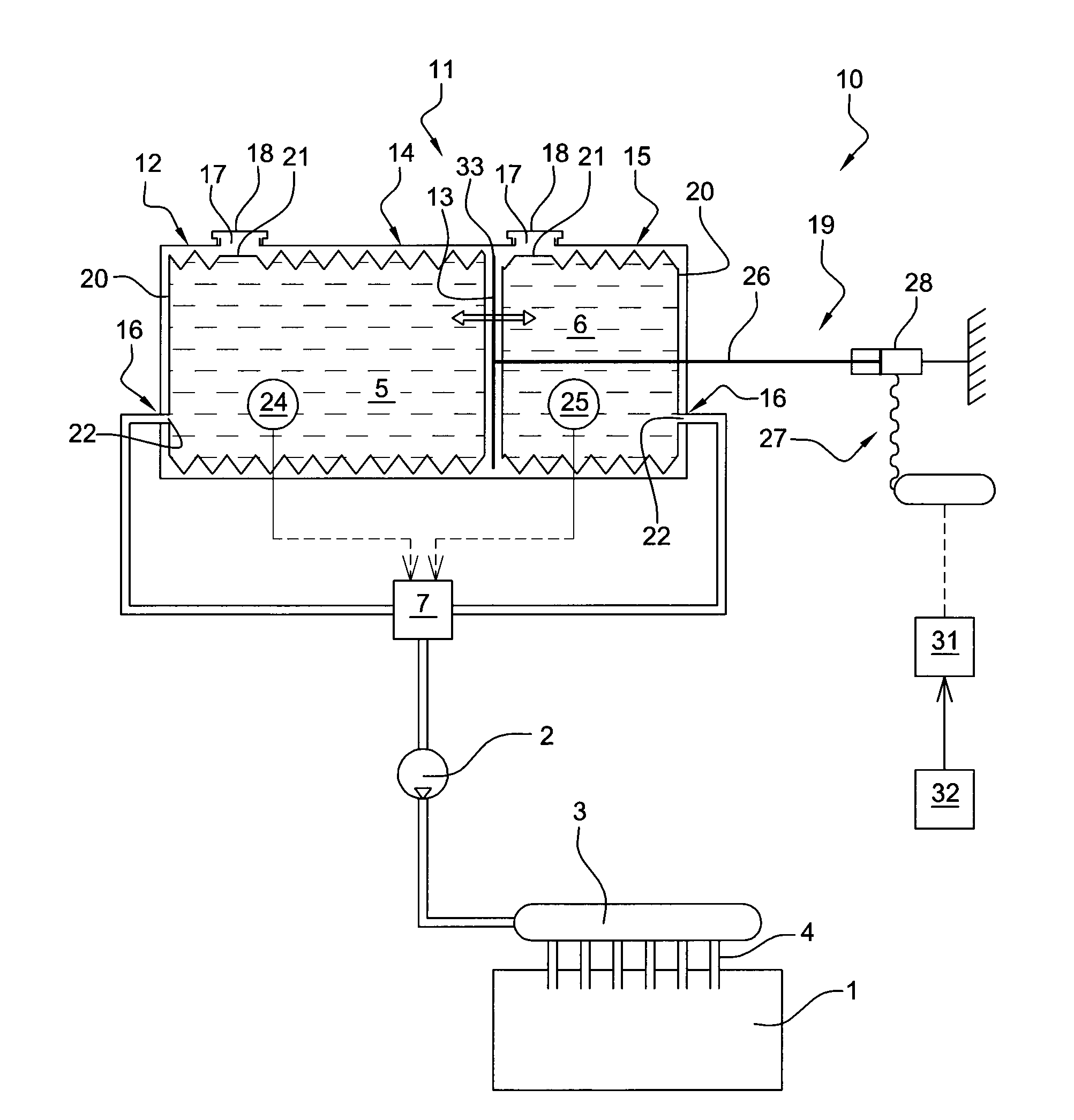
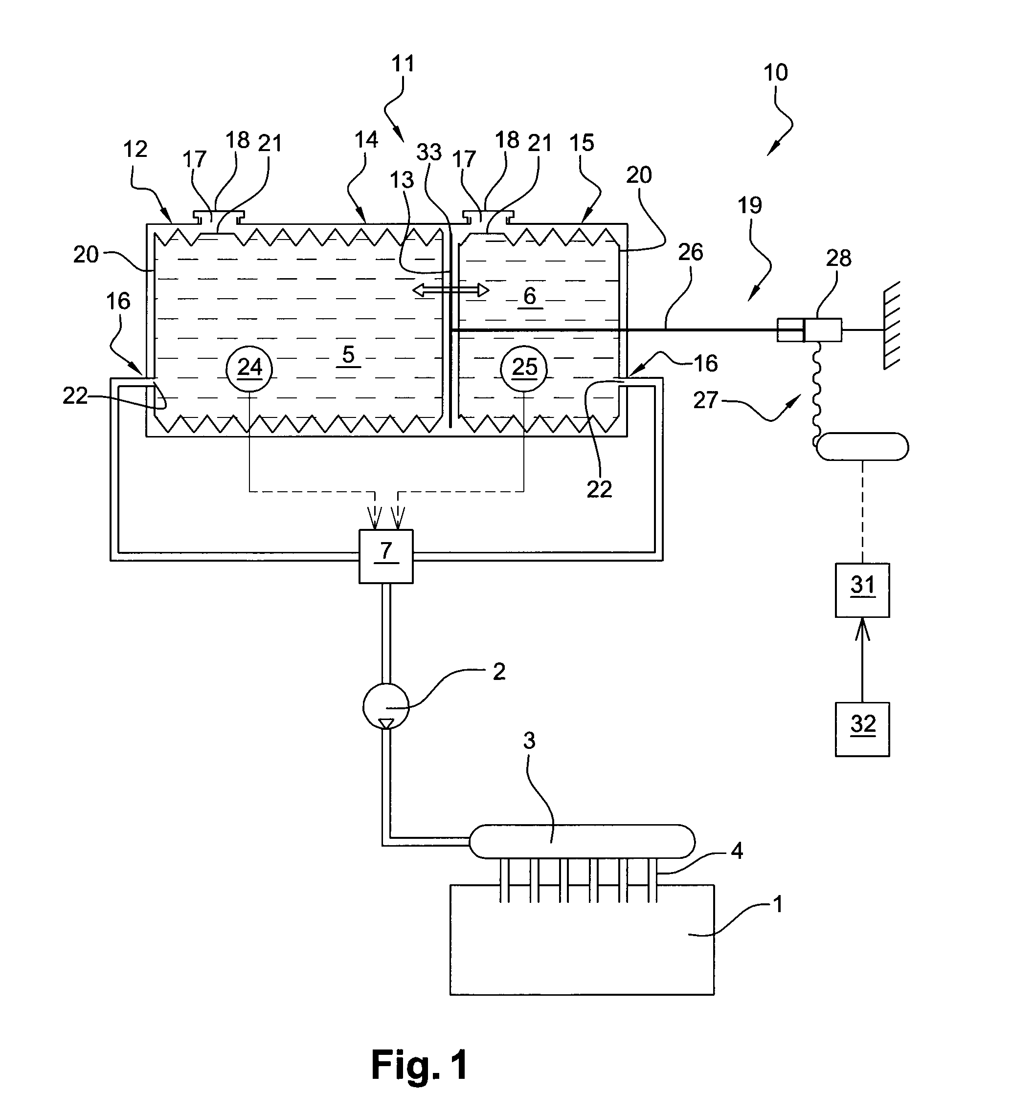
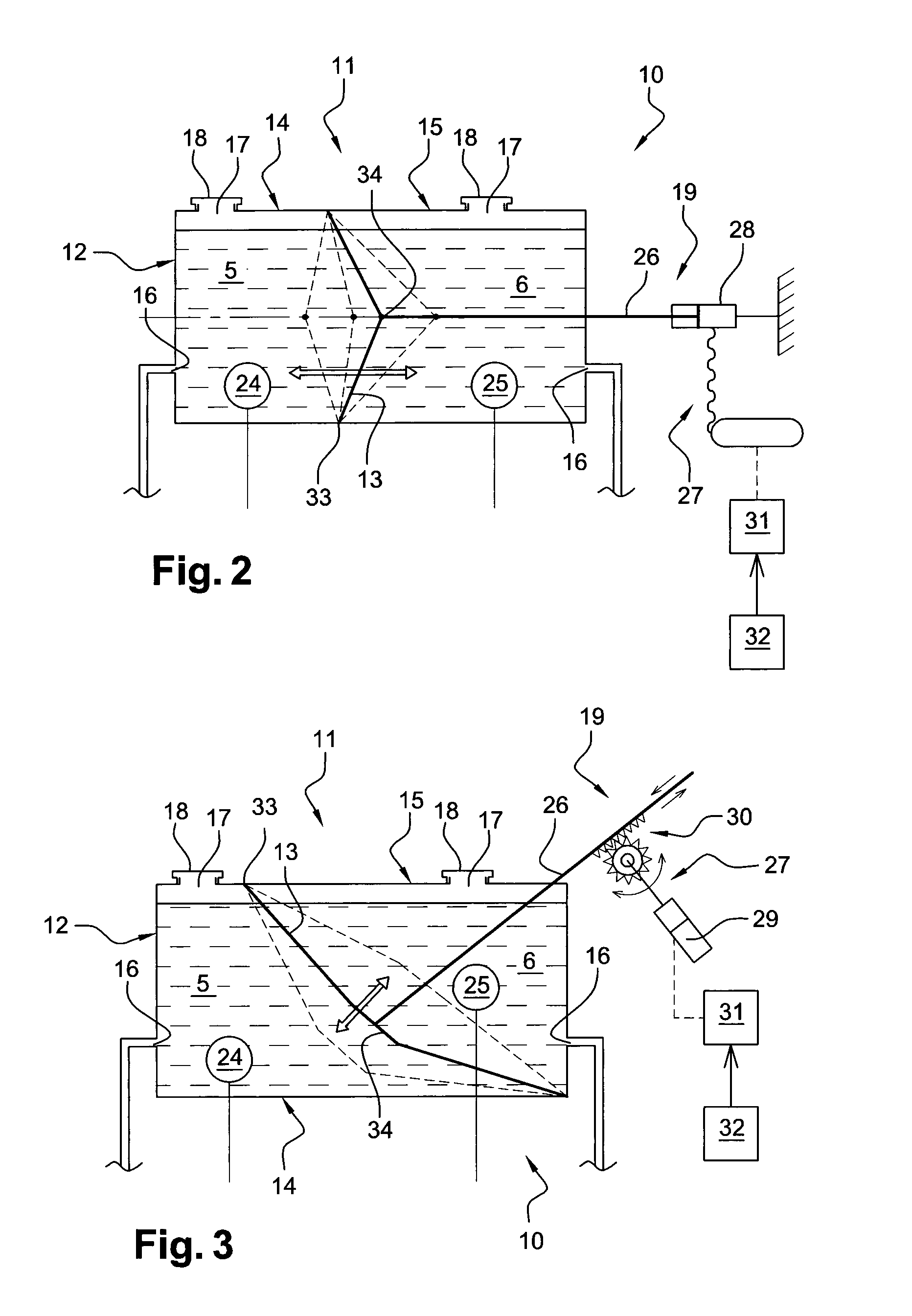
[0075]Reference is now made to FIG. 1 which shows the invention.

[0076]In this embodiment, the partition wall 13 can be substantially rigid and can be moved inside the tank 12. In other words, the partition wall 13 can resist the deformation stresses, and its shape remains substantially unchanged during normal operating conditions. However, the partition wall 13 is displaceable altogether inside the tank.

[0077]For example, the partition wall 13 can comprise a plate, for example a metal plate. This plate can be arranged substantially transversally to the tank 12, thereby defining compartments 14, 15 on both sides. There may be provided a sealing means (not shown) at the periphery 33 of the partition wall 13, in order to prevent fluid links between compartments 14, 15. Alternatively or additionally, flexible bags 20 as previously described can be used to contain the fluids 5, 6.

[0078]The actuator 19 can be provided to move the partition wall 13 inside the tank 12. The moving member 26 ...


PUM


Abstract

A vehicle fuel tank arrangement is provided for a fuel that includes at least a first fluid and a second fluid. The tank arrangement includes a tank and a partition wall arranged inside the tank in order to create at least a first compartment for storing the first fluid and a second compartment for storing the second fluid. The position of the partition all inside the tank can be changed to set the volume of the first compartment and the second compartment to predetermined values.

Description

BACKGROUND AND SUMMARY[0001]The present invention relates to a vehicle fuel tank arrangement and to a method for managing the supply of fuel to a vehicle engine, said fuel comprising at least a first fluid and a second fluid.[0002]In some cases, it may be advantageous to supply a vehicle engine with a fuel which is a mixture of two or more fluids.[0003]For example, using a dual fuel composed of gasoline and diesel can have positive impacts on the overall consumption or on the engine functioning, especially by reducing knocking and / or by improving ignition.[0004]Since the composition of the optimal fuel changes as a function fit the vehicle operational conditions, it has been proposed not to use a fuel having a predetermined and fixed composition but to create the appropriate mixture depending on said conditions. Therefore, it is known to provide a tank for each fluid which will form part of the fuel supplied to the vehicle engine, and to adapt the fluids ratio in the fuel according ...

Claims


Application Information

Patent Timeline
Patent Type & Authority Applications(United States)
IPC IPC(8): B60K15/03
CPCB60K15/03006B60K2015/03131B60K2015/03157B60K2015/03355B60K15/077F02M37/0088F02D19/0665Y02T10/30
Inventor BALLOUL, IYADPALMER, JEAN-CHRISTOPHEVANVOLSEM, MICHEL
Owner VOLVO LASTVAGNAR AB
Why Eureka
Try Eureka