Current sensor

a current sensor and current path technology, applied in the field of current sensor, can solve the problems of inability to obtain stable detection values of magnetoelectric conversion elements (cb>15/b>, cb>25/b>), and the size of the current sensor cannot be reduced any further, so as to achieve the effect of further reducing the effect of external magnetic fields from neighboring current paths

Active Publication Date: 2014-10-30
ALPS ALPINE CO LTD
View PDF2 Cites 10 Cited by
  • Summary
  • Abstract
  • Description
  • Claims
  • Application Information

AI Technical Summary

Benefits of technology

[0023]According to this configuration, the current path to be measured, and a neighboring current path disposed at a position neighboring the current path to be measured, are disposed on the second imaginary line, so the neighboring current path is situated on the outside of the first magnetoelectric conversion element group or on the outside of the second magnetoelectric conversion element group, meaning that the neighboring current path is situated on the outside of a magnetoelectric conversion element group of which the element spacing is narrower than the group spacing. Thus, the effects of external magnetic fields from neighboring current paths can be further reduced, and the effects of external magnetic fields on the magnetoelectric conversion elements can be even further reduced, so detection values from the magnetoelectric conversion elements can be obtained in an even more stable manner.

Problems solved by technology

Accordingly, there has been a problem in that the size of the current sensor could not be reduced any further, since there is need to ensure dimensions between the magnetoelectric conversion elements to allow passage of the current path to be measured.
Further, the element spacings (DC1, DC2) are spread to where the current path CB to be measured can pass, so there is a problem in that in a case where there are other neighboring current paths CN in the neighborhood, stable detection values from the magnetoelectric conversion elements (C15, C25) cannot be obtained due to influence of the external magnetic field from the neighboring current paths CN.

Method used


Image

  • Current sensor
  • Current sensor
  • Current sensor

Examples


first embodiment

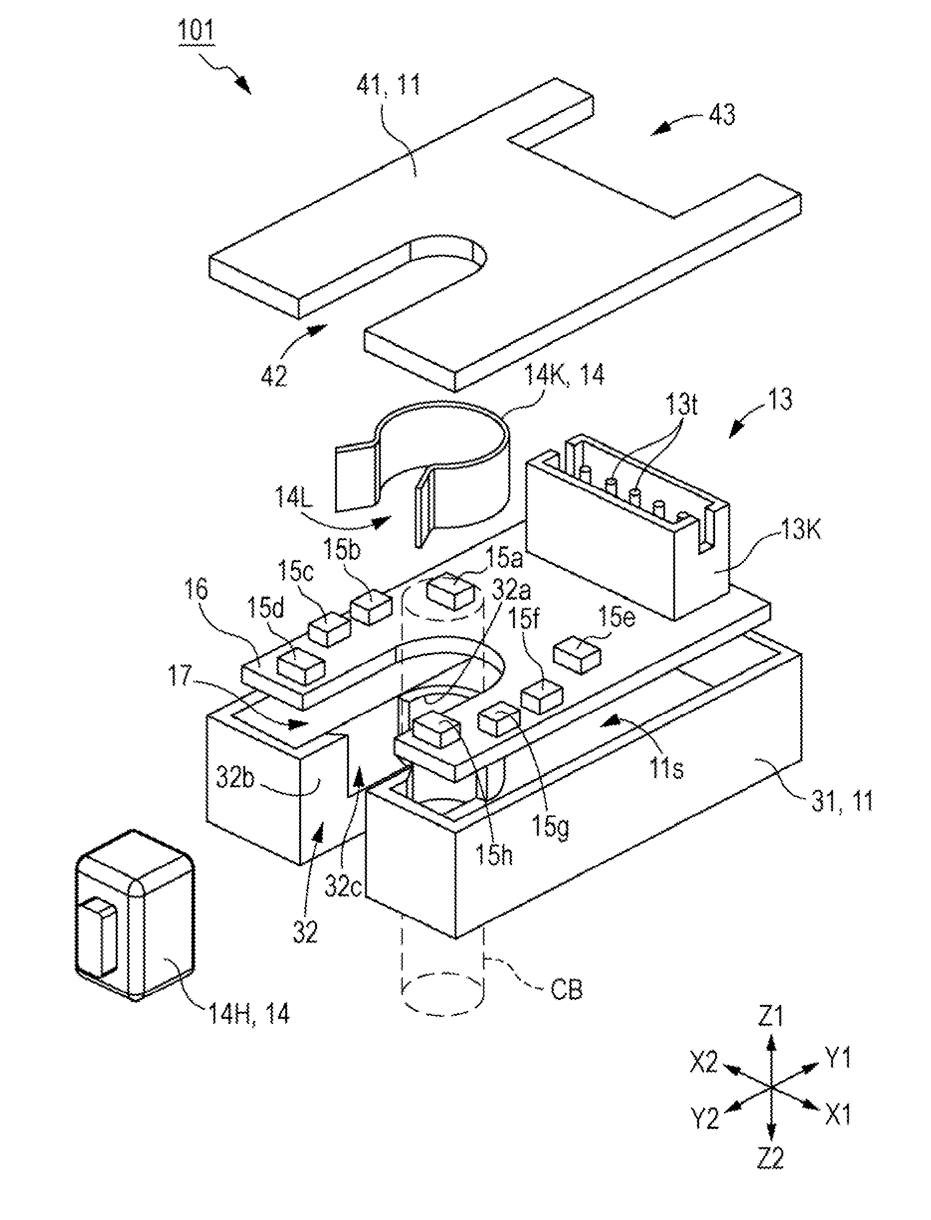
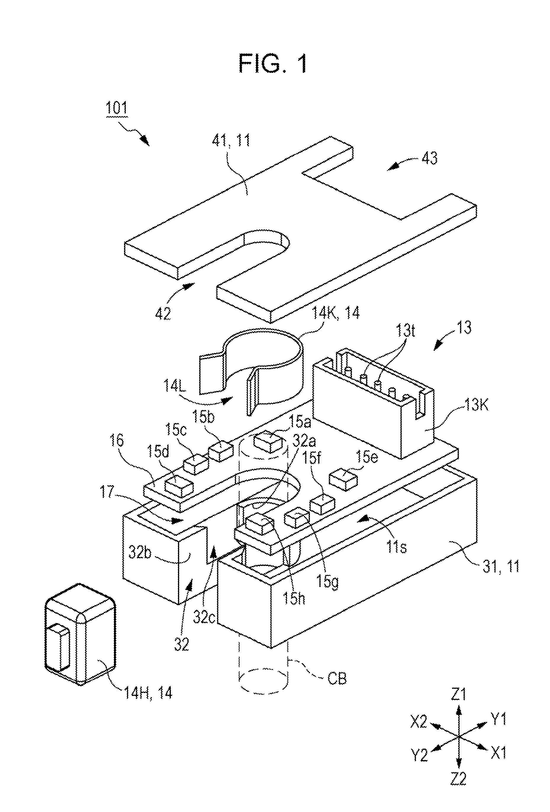
[0044]FIG. 1 is a disassembled perspective view illustrating a current sensor 101 according to a first embodiment of the present invention. FIG. 2 is a perspective view of the current sensor 101 according to the first embodiment of the present invention. FIG. 3 is a plan view for describing the current sensor 101 according to the first embodiment of the present invention, illustrating a wiring board 16 as viewed from the Z1 side shown in FIG. 1. FIG. 14 is a layout diagram for describing a comparative example in comparison with the current sensor 101 according to the first embodiment of the present invention, illustrating magnetoelectric conversion elements according to a comparative example 3 in comparison with the layout of magnetoelectric conversion elements 15 in FIG. 3.

[0045]The current sensor 101 according to the first embodiment is configured including multiple magnetoelectric conversion elements 15 which detect magnetism generated when a current flows through a current path ...

second embodiment

[0073]FIG. 9 is a disassembled perspective view illustrating a current sensor 102 according to a second embodiment of the present invention. FIG. 10 is a plan view of the current sensor 102 according to the second embodiment of the present invention, illustrating a wiring board 16 as viewed from the Z1 side shown in FIG. 9. FIG. 15 is a layout diagram for describing a comparative example in comparison with the current sensor 102 according to the second embodiment of the present invention, illustrating magnetoelectric conversion elements according to a comparative example 4 in comparison with the layout of magnetoelectric conversion elements 25 in FIG. 10. The placement positions of the magnetoelectric conversion element 25 in the current sensor 102 according to the second embodiment are different from those in the first embodiments. Configurations where are the same as in the first embodiment are denoted with the same reference numerals, and detailed description thereof will be omit...

first modification

[0092]FIGS. 16A and 16B are diagrams for describing a first modification of the current sensor 101 according to the first embodiment of the present invention. FIG. 16A is a model diagram of the first modification as compared with the model diagram in FIG. 4, and FIG. 16B is a graph illustrating calculation results of calculations performed based on a model using the Biot-Savart law. FIG. 16A illustrates the elliptical array of the magnetoelectric conversion elements 15 of the current sensor 101 according to the first embodiment of the present invention, the octagonal layout of the magnetoelectric conversion elements C35 according to comparative example 3, and a hexagonal array of magnetoelectric conversion elements M15 according to the first modification. The horizontal axis in FIG. 16B represents the amount of movement where the neighboring current path CN1 has shifted in the Y1 direction (illustrated in FIG. 4), and the vertical axis represents the error of the output values outpu...


PUM


Abstract

A first magnetoelectric conversion element group including magnetoelectric conversion elements, and a second magnetoelectric conversion element group including magnetoelectric conversion elements are arranged across a cutout of a wiring board. The first and second groups are arranged line-symmetrically with respect to a first imaginary line. The elements in the first and second groups are arranged line-symmetrically with respect to a second imaginary line. The first imaginary line and the second imaginary line orthogonally intersect each other at a placement position at which a current path to be measured is placed. The orientation of the sensitivity axis of each of a plurality of magnetoelectric-conversion-element sets having point symmetry about the placement position is parallel or antiparallel. An element spacing, which is spacing between neighboring elements in the first and second groups, is narrower than a group spacing, which is the narrowest spacing between the first and second groups.

Description

CLAIM OF PRIORITY[0001]This application is a Continuation of International Application No. PCT / JP2013 / 051535 filed on Jan. 25, 2013, which claims benefit of Japanese Patent Application No. 2012-041612, filed on Feb. 28, 2012 and No. 2012-125042, filed May 31, 2012. The entire contents of each application noted above are hereby incorporated by reference.BACKGROUND OF THE INVENTION[0002]1. Field of the Invention[0003]The present invention relates to a current sensor which detects an electric current flowing through a current path to be measured, and more particularly relates to a current sensor which detects an electric current flowing through a current path to be measured, using a magnetoelectric conversion element.[0004]2. Description of the Related Art[0005]Current sensors which are attached to a current path to be measured and detect electric currents flowing through the current path to be measured, in order to control or monitor various types of electronic equipment, are well kno...

Claims


Application Information

Patent Timeline
Patent Type & Authority Applications(United States)
IPC IPC(8): G01R19/00
CPCG01R19/0092G01R15/207G01R33/02G01R33/09G01R33/093
Inventor FUKUI, HIROFUMI
Owner ALPS ALPINE CO LTD
Why Eureka
Try Eureka