Antenna device

a technology of antenna device and coaxial cable, which is applied in the direction of polarised antenna unit combination, stripline fed array, particular array feeding system, etc., can solve the problems of non-negligible loss in the connecting portion of the coaxial cable, limit the enhancement of the efficiency of the antenna device, and the loss of coaxial cable is not negligible, so as to reduce the dielectric loss, enhance the efficiency, and suppress the loss

Active Publication Date: 2014-10-30
HITACHI METALS LTD
View PDF4 Cites 4 Cited by
  • Summary
  • Abstract
  • Description
  • Claims
  • Application Information

AI Technical Summary

Benefits of technology

[0022]The antenna device according to the present invention can lower dielectric loss in a feed line providing power to the antenna elements to thereby ensure the enhancement of the efficiency, and also allows omission of a transmission line connecting portion to enable the suppression of the occurrence of loss.

Problems solved by technology

However, in the conventional antenna device, a coaxial cable with a dielectric for insulating a center conductor and an outer conductor as the feed line has been used, the dielectric loss in the coaxial cable is not negligible, and there is a limit on the enhancement of the efficiency of the antenna device.
Further, when the power distributor, the phase shift adjusting transmission line, and the feed line are different in line structure, non-negligible loss in the connecting portion thereof may occur.

Method used


Image

  • Antenna device
  • Antenna device
  • Antenna device

Examples


Embodiment Construction

.

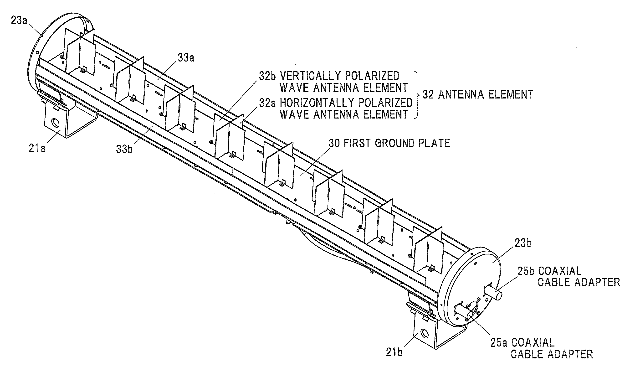
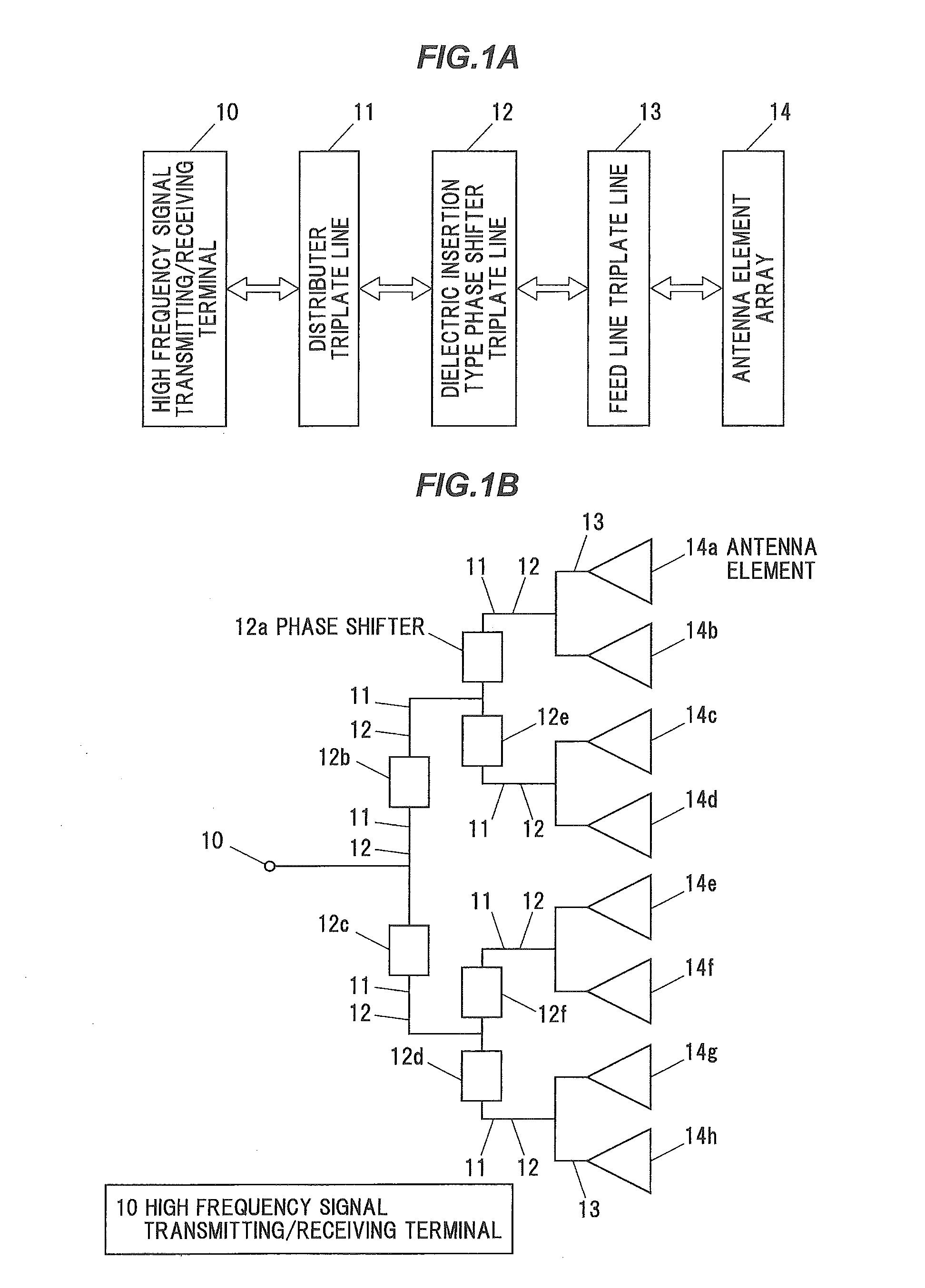
[0042]1A is a block diagram showing a configuration example of a schematic of a mobile phone base station antenna device 1 in an embodiment according to the present invention. This mobile phone base station antenna device 1 includes a high frequency signal transmitting / receiving terminal 10, a distributor triplate line 11, a dielectric phase shifter triplate line 12, and a feed line triplate line 13, and an antenna element array 14 with antenna elements arranged in an array.

[0043]In this configuration, when excitation power is input to the high frequency signal transmitting / receiving terminal 10 as a high frequency transmission signal, the excitation power is distributed by the distributor triplate line 11 as a distributing portion. The excitation power distributed is imparted with a predetermined amount of phase shift by the dielectric phase shifter triplate line 12 as a respective corresponding phase shifting portion, and is input to the feed line triplate line 13 as a respective...


PUM


Abstract

An antenna device includes an input/output portion for a high frequency signal to be input or output, a distributing portion for distributing the high frequency signal input to the input/output portion into a plurality of high frequency signals, a phase shifting portion for imparting the plurality of high frequency signals with a predetermined amount of phase shift, and a feeding portion for feeding a plurality of antenna elements with the plurality of high frequency signals imparted with the predetermined amount of phase shift to cause the plurality of antenna elements to radiate the plurality of high frequency signals. The feeding portion is configured as a triplate line with a center conductor placed between one pair of parallel plate shaped outer conductors.

Description

[0001]The present application is based on Japanese patent application No. 2013-91604 filed on Apr. 24, 2013, the entire contents of which are incorporated herein by reference.BACKGROUND OF THE INVENTION[0002]1. Field of the Invention[0003]This invention relates to an antenna device for feeding a plurality of antenna elements with a high frequency signal imparted with an amount of phase shift by a phase shifter.[0004]2. Description of the Related Art[0005]As an example of conventional antenna devices, it has been known an antenna device with a combination of a rotary phase shifter and a phase shift amount adjustment transmission line of a predetermined length, so that the tilt angle is altered by adjusting the rotation angle of the rotary phase shifter. This antenna device is configured so that excitation power inputted to an input terminal is distributed by a power distributor, and this distributed power is input to the rotary phase shifter, and output of the rotary phase shifter is...

Claims


Application Information

Patent Timeline
Patent Type & Authority Applications(United States)
IPC IPC(8): H01Q21/00H01Q1/48
CPCH01Q1/48H01Q21/0031H01Q1/246H01Q3/36H01Q21/0081H01Q21/26
Inventor ISO, NAOKIKITANO, NOBUAKIOGAWA, TOMOYUKIISHIGAMI, YOSHIAKI
Owner HITACHI METALS LTD
Why Eureka
Try Eureka