Eureka AIR delivers breakthrough ideas for toughest innovation challenges, trusted by R&D personnel around the world.

Three dimensional display system

a display system and three-dimensional technology, applied in the field of three-dimensional display systems, can solve the problems of low display resolution, inconvenient use of swept-volume displays as interactive devices, and inability to use them as interactive devices

Active Publication Date: 2014-11-06
KONG LIANG
View PDF19 Cites 20 Cited by
  • Summary
  • Abstract
  • Description
  • Claims
  • Application Information

AI Technical Summary

Benefits of technology

This patent describes a way to create a 3D image from multiple 2D images taken from different angles. This allows the user to view the image from many angles like they would a real object. This method also benefits from using small image components as each one has a narrow field of view, which reduces optical aberration. Additionally, this method improves the user's awareness and understanding of the interconnected nature of different websites, making it easier to navigate back-track to previously visited pages and absorb information more easily.

Problems solved by technology

However, such systems are suitable only for viewing by a single viewer.
However, since the display volume in such devices must include a rapidly moving mechanical part, use of a swept-volume display as an interactive device is impossible, since the image cannot be touched without causing injury.
These displays are also unsuitable for use in mobile devices such as laptops, tablets and phones.
Such displays do not require moving parts in the display volume, but the displayed image is made up of relatively large pixels, so the display resolution is low.
However, known holographic displays do not offer user interaction.
A virtual, as opposed to real, image cannot be touched and therefore cannot offer user interaction.

Method used


Image

  • Three dimensional display system
  • Three dimensional display system
  • Three dimensional display system

Examples


Embodiment Construction

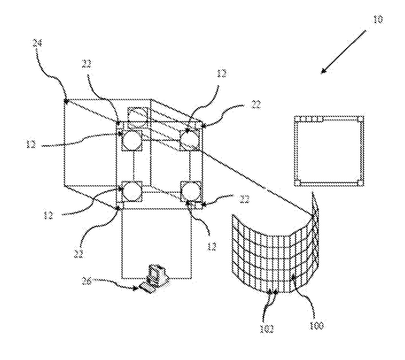
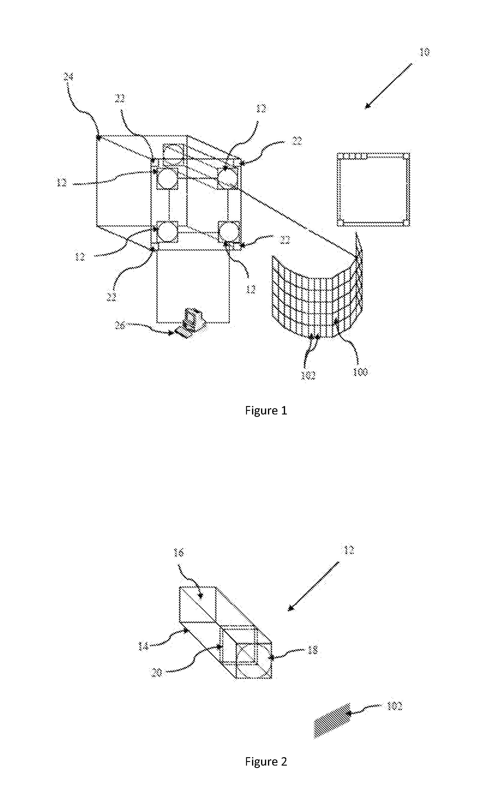
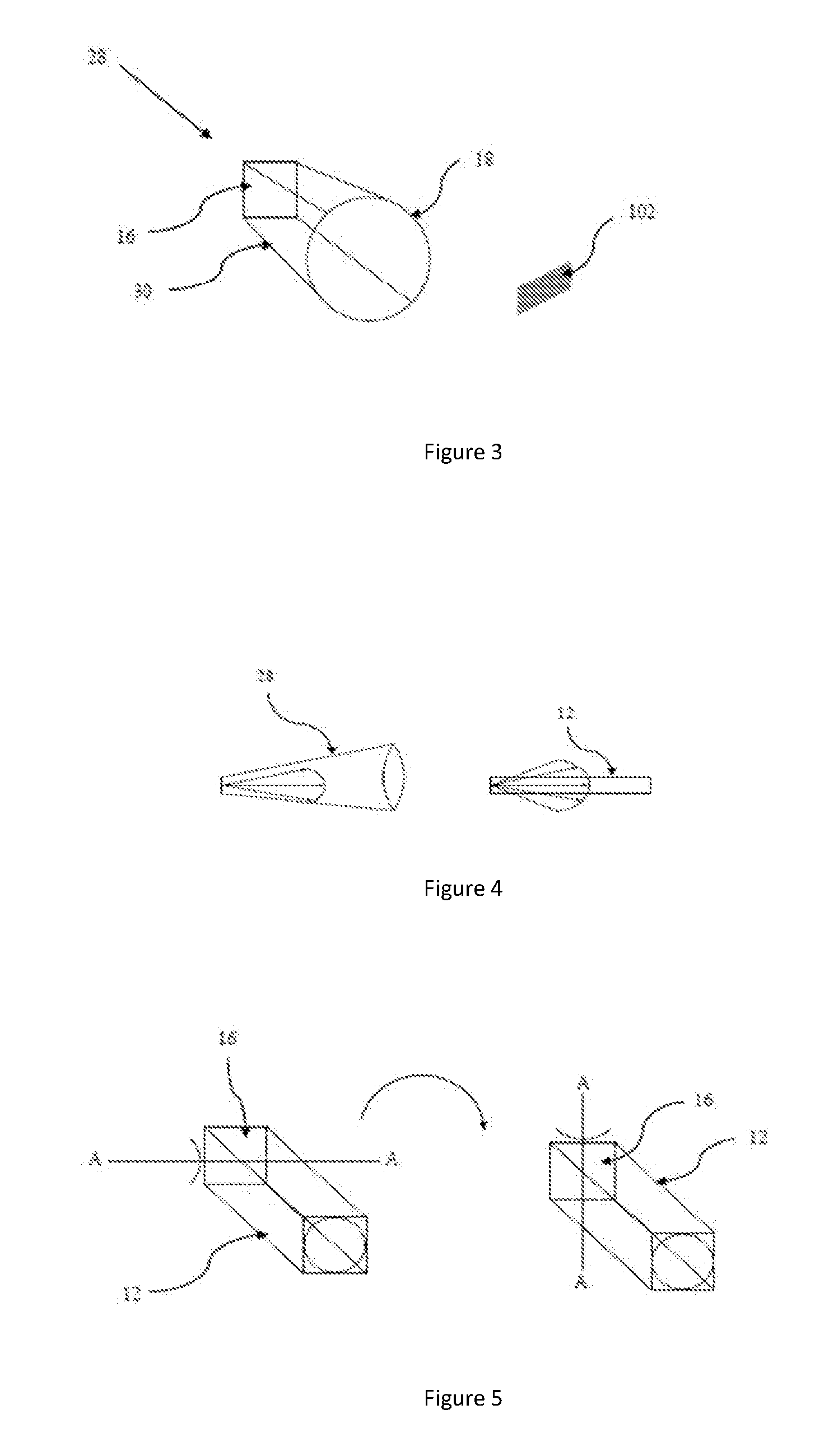
[0071]Referring firstly to FIG. 1, a three-dimensional display system is indicated generally at 10. The display system 10 comprises a plurality of projection blocks 12, a plurality of cameras 22, a display housing 24 and a computer 26. Each projection block 12 projects a two-dimensional image component 102 into the space in front of the display system 10. The two-dimensional image components 102 combine to form a three-dimensional image 100.

[0072]The structure of each projection block 12 is illustrated in FIG. 2. Each projection block comprises a block housing 14, a two-dimensional display screen 16, a zoom lens 18 and a modulator 20. The housing 14 is in the shape of an elongate square prism. The two-dimensional display screen 16 is at one end of the elongate housing 14 and the zoom lens 18 is at the opposing end. The modulator 20 is disposed at substantially one quarter of the distance between the ends, closer to the zoom lens 18 than the display screen 16.

[0073]The two-dimensiona...


PUM


Abstract

A three-dimensional display system (10) comprises a display housing (24) and a plurality of projectors (12) for projecting two-dimensional images (102) into a space, each projector (12) having means to adjust the distance between the projector (12) and the projected image (102), and each projector (12) being pivotally mounted to the display housing (24), for adjusting the horizontal and vertical position of the projected two-dimensional image (102) with respect to the projector (12). The display provides a high-resolution, three-dimensional multi-coloured image which can be touched safely by the viewer. The display may be respond to physical objects in the display area by altering the image. The display may be used to operate a computer and browse the world wide web.

Description

[0001]The present invention relates to a three-dimensional display and particularly but not exclusively to a three-dimensional display allowing user interaction.BACKGROUND TO THE INVENTION[0002]Three-dimensional display systems are well known and fall into several technical categories. Stereoscopic systems rely on presenting two different images to the two eyes of a viewer. This may be achieved by projecting two images onto the same screen, and providing a viewer with polarized glasses or glasses with coloured filters so that a first image is seen only by the viewer's right eye, and a second image is seen only by the viewer's left eye. Autostereoscopic systems, which do not require glasses, are also available and present separate images to each eye via a parallax barrier or lenticular array.[0003]In stereoscopic systems, the images which are presented to the left and right eyes of the viewer are the same images, whatever the position of the viewer with respect to the image. The view...

Claims


Application Information

Patent Timeline
IPC IPC(8): H04N13/04G03B35/20
CPCH04N13/0459H04N9/3147H04N9/3194G06F3/017G06F3/04815H04N13/349H04N13/207H04N13/363H04N13/366G02B30/56G03B35/20H04N13/388H04N5/74H04N13/302G03B21/60
Inventor KONG, LIANG
Owner KONG LIANG
Why Eureka
Eureka Blog
Learn More