Machine for punching panels

a technology for punching panels and printed circuits, which is applied in the direction of large fixed members, electrical appliances, printed circuit manufacture, etc., can solve the problems of spoiling the precision with which the hole is positioned, affecting the accuracy with which the punch is finally positioned, and the configuration of cantileverings running the risk of being prejudicial to the precision with which the punch is positioned, etc., to achieve the effect of simplifying the final positioning operation, reducing the drawbacks of prior

Inactive Publication Date: 2002-10-22
AUTOMA TECH
View PDF13 Cites 8 Cited by
  • Summary
  • Abstract
  • Description
  • Claims
  • Application Information

AI Technical Summary

Benefits of technology

An object of the present invention is to provide a machine for punching a panel, and in particular a printed circuit panel, which mitigates the drawbacks of prior art machines while enabling the operating throughput of the machine to be increased, in particular by simplifying the final positioning operations performed between the panel and the punch tools.
It will be understood that in the invention the panel is fixed relative to the structure after it has been prepositioned, and that it is the punch blocks which are positioned with precision in the X and Y directions and in rotation in order to make holes at the intended locations on the panel and to make holes with the desired orientations. It can thus be seen that since the panel is fixed relative to the structure, it is possible to provide means for preventing the panel from moving relative to the structure which are more effective and simpler since these means for holding the panel stationary are themselves functionally fixed relative to the structure.
In addition, the fact that the supports for the punch blocks of at least two of the punch blocks are in the form of a gantry means that the panels can pass between the punch and the die when feeding a panel to the machine and when removing a panel therefrom after the holes have been made.
In this preferred embodiment, the fact that the camera is secured to the punch block and that the block is itself prepositioned means that the camera need have only a small field of view, thereby giving an image that is more precise.
This operation which is itself made possible by having precise control over the positioning of each punch block in the X and Y directions and in rotation, makes it possible in turn to escape from the cumulative effect of manufacturing tolerances concerning the various parts of the punch tools.

Problems solved by technology

In certain types of manufacture, it is found that positioning the printed circuit panel relative to the machine can take up a non-negligible length of time, in particular because of the large dimensions of the panel to be positioned.
Further, while the punching operation is being performed, the panel must be held with very great precision while simultaneously avoiding any risk of bending the panel since that would spoil the precision with which the hole is positioned.
Unfortunately, it is naturally necessary to have access to both faces of the panel so as to be able to place on opposite sides thereof firstly the punch proper and secondly the die which is associated with the punch.
The resulting cantilevered-out configuration would run the risk of being prejudicial to the precision with which the punch is finally positioned.

Method used


Image

  • Machine for punching panels
  • Machine for punching panels
  • Machine for punching panels

Examples


Embodiment Construction

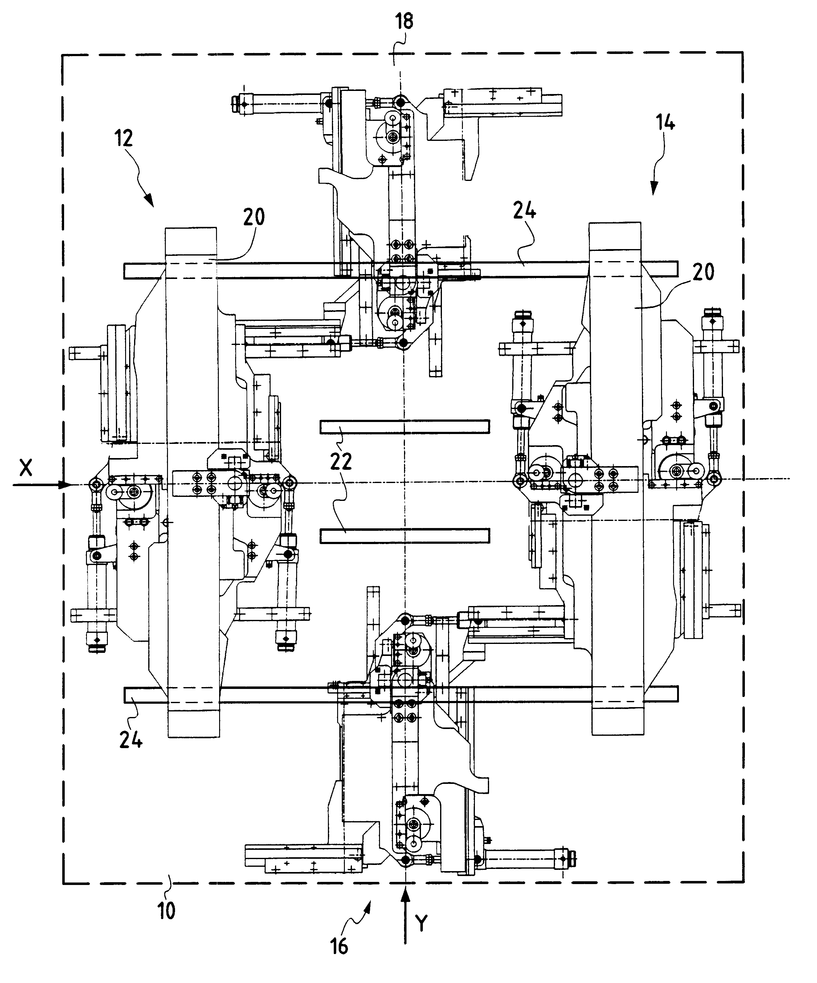
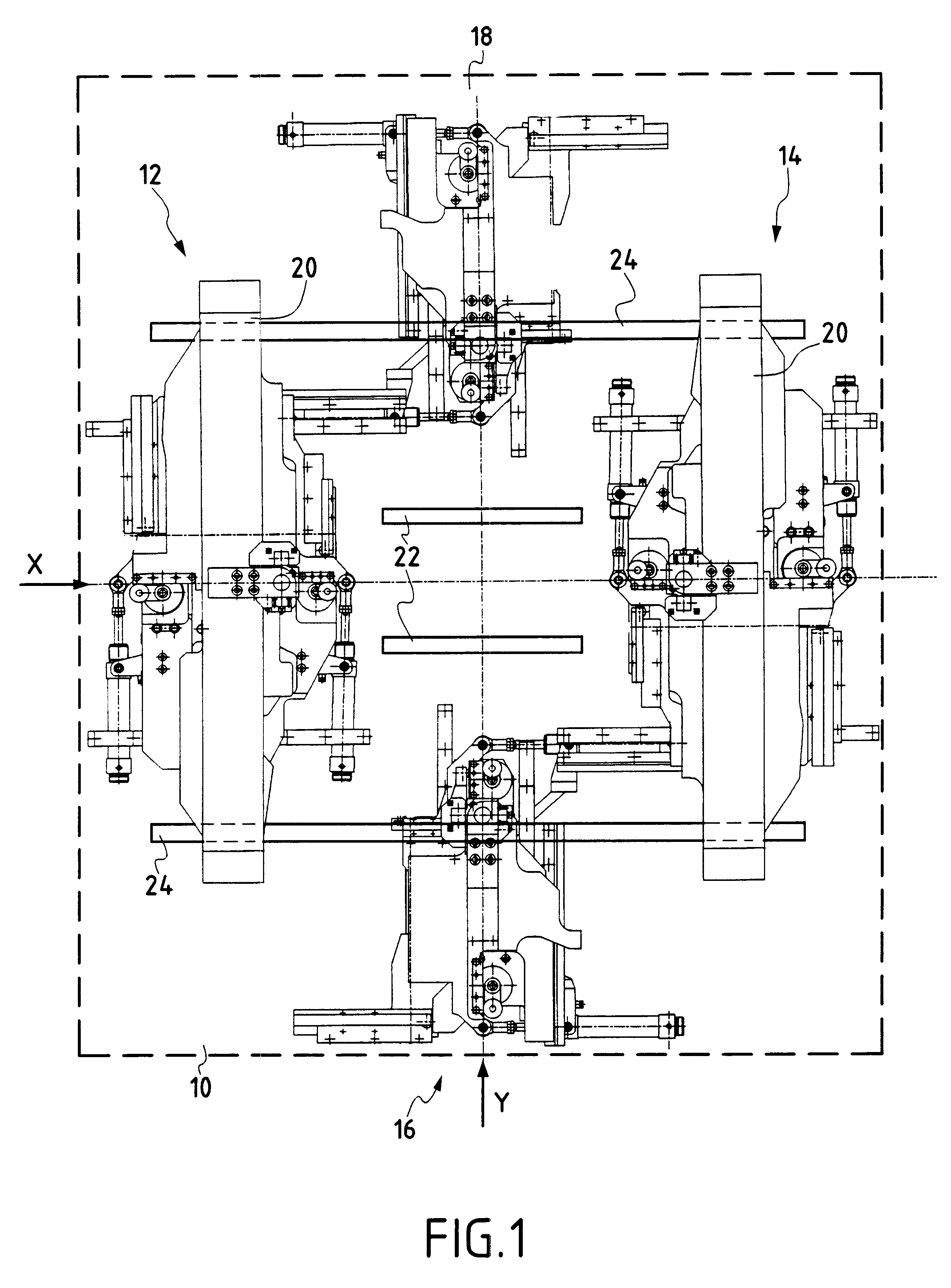
FIG. 1 shows all of the main elements of the punch machine. The figure shows the structure 10 of the machine and four moving punch blocks respectively referenced 12, 14, 16, and 18. The structure 10 identifies a direction X which corresponds to the direction in which printed circuit panels are inserted into the punch machine and a direction Y which is orthogonal thereto. The punch blocks 12 and 14 are connected to the structure 10 via portal- or gantry-forming structures 20 so as to allow the printed circuit panels to pass through. This figure also shows diagrammatically drive means 22 for driving the panels so as to bring them into a prepositioning position relative to the machine as a whole, and guide and holding means 24 for guiding and holding the printed circuit panels. The means 24 are essentially constituted by two assemblies enabling the edges of the printed circuit panels to be clamped in the X direction and for applying tension between these clamp elements so as to ensure ...


PUM

PropertyMeasurementUnit
rotation position erroraaaaaaaaaa
displacementaaaaaaaaaa
dimensionsaaaaaaaaaa

Abstract

The invention relates to a punch machine for punching a panel in which the position of each hole to be made is identified by a mark. The machine comprises a structure for receiving said panel, said structure presenting X and Y directions; means for holding said panel relative to the structure; at least four punch blocks secured to a support, each punch block having at least one punch carrier tool and at least one matrix carrier assembly; means for displacing each punch block separately in the X and Y directions and in rotation; optical means for comparing the position of each punch block with said mark; and means for separately controlling the displacement means in response to position error information.

Description

The present invention relates to a machine for punching panels and in particular printed circuit panels.More and more items of equipment are making use of printed circuits that are becoming ever more complex. To solve this problem, it is common place to use multilayer printed circuits. Such multilayer circuits consist in making some number of individual printed circuit plates or panels which are then fixed together and electrical connections are also made between the various layers so as to obtain a complete multilayer printed circuit.When making the complete circuit, it is naturally necessary to stack the individual printed circuits with great precision in order to succeed in making the final circuit, so it is essential to provide position-marker means in each of the individual printed circuits. This marking is usually performed by means of holes formed through the insulating backing of the printed circuit at locations that are well defined relative to the panel and / or the printed ...

Claims


Application Information

Patent Timeline
Patent Type & Authority Patents(United States)
IPC IPC(8): B23Q1/62B23Q1/25B26F1/02B26D7/26H05K3/00H05K1/02
CPCB23Q1/625B26D7/2628B26F1/02H05K3/005B26F2210/08H05K1/0269H05K3/0008Y10T83/4604Y10T83/538Y10T83/4463Y10T83/8742Y10T83/173Y10T83/8847Y10T83/447
Inventor CHARBONNIER, SERGE
Owner AUTOMA TECH
Why Eureka
Try Eureka