Eureka AIR delivers breakthrough ideas for toughest innovation challenges, trusted by R&D personnel around the world.

Light collecting system with a number of reflector pairs

Active Publication Date: 2014-11-06
MARTIN PROFESSIONAL
View PDF0 Cites 24 Cited by
  • Summary
  • Abstract
  • Description
  • Claims
  • Application Information

AI Technical Summary

Benefits of technology

The present invention is about a light collector for an illumination device that collects light from multiple light sources and combines it into a common light beam. The invention aims to create an illumination device that is energy efficient and capable of illuminating very bright light beams. The invention is particularly useful in the entertainment industry for creating effects and mood lighting. The invention uses LEDs, which are becoming more popular in lighting applications due to their low energy consumption and high efficiency. However, previous attempts to create optical systems where the light sources are arranged around the optical axis and the light is emitted towards the optical axis in a direction substantially perpendicular to the optical axis have not been very efficient, resulting in low light output pr. power unit. The invention solves this problem by creating a light collector that is more efficient and capable of creating brighter light beams.

Problems solved by technology

However this is hard to achieve in projecting systems where the light in general is collected through an optical gate, which is imaged onto a target surface using an imaging optical system.
However these systems are not very efficient as there is a relatively high loss of light due the fact that the top part of the light beams will pass the narrow top / tip of the cone or pyramid reflector rather than being reflected alone the optical axis.
Further loss occurs when the common light beam is directed to an optical gate and later collected by a projecting system.
However in illumination devices it is desired to use ordinary LEDs which, however, as which due to etendue issues cannot produce as narrow and parallel light beams as laser devices.
As a consequence there will be a large loss of light if the laser devices of EP 0978748 were replaced by ordinary LEDs, as a large part of the light reflected by the first reflector will not hit the second reflector due the fact the second reflector narrows down at the top of the cone.
Yet another issue is the fact that ordinary LED due to the manufacturing process typically are provided with rectangular dies and as a consequence the light guiding element needs to be event longer in order to mix the light beams properly.
This illumination device is thus not usable in projecting systems where an image of a light modifier needs to be projected to a projecting surface.
This is often not possible when using a spherical symmetric optical system, as LEDs, due the manufacturing process, typically are provided polygonal shaped especially rectangular shapes
The consequence is, however, that the efficiency with regard to power consumption versus light output is very low.
Furthermore, a large amount of light is lost as the prior art fixtures typically only couple a central part of the light of the light beams through the gate in order to provide a uniform illumination of the gate, which again reduces the efficiency.
The available space in light fixtures is often limited and it is difficult to fit many light sources into prior art fixtures, for instance because the optical components associated with the light sources often take up a lot of space.
Yet another aspect is the fact that color artifacts often appear in the output from fixtures having light sources of different colors.

Method used


Image

  • Light collecting system with a number of reflector pairs
  • Light collecting system with a number of reflector pairs
  • Light collecting system with a number of reflector pairs

Examples


Embodiment Construction

[0017]The object of the present invention is to solve the above described limitations related to prior art and provide a compact projecting illumination device. This is achieved by an illumination device as described in the independent claims. The dependent claims describe possible embodiments of the present invention. The advantages and benefits of the present invention are described in the detailed description of the invention.

DESCRIPTION OF THE DRAWING

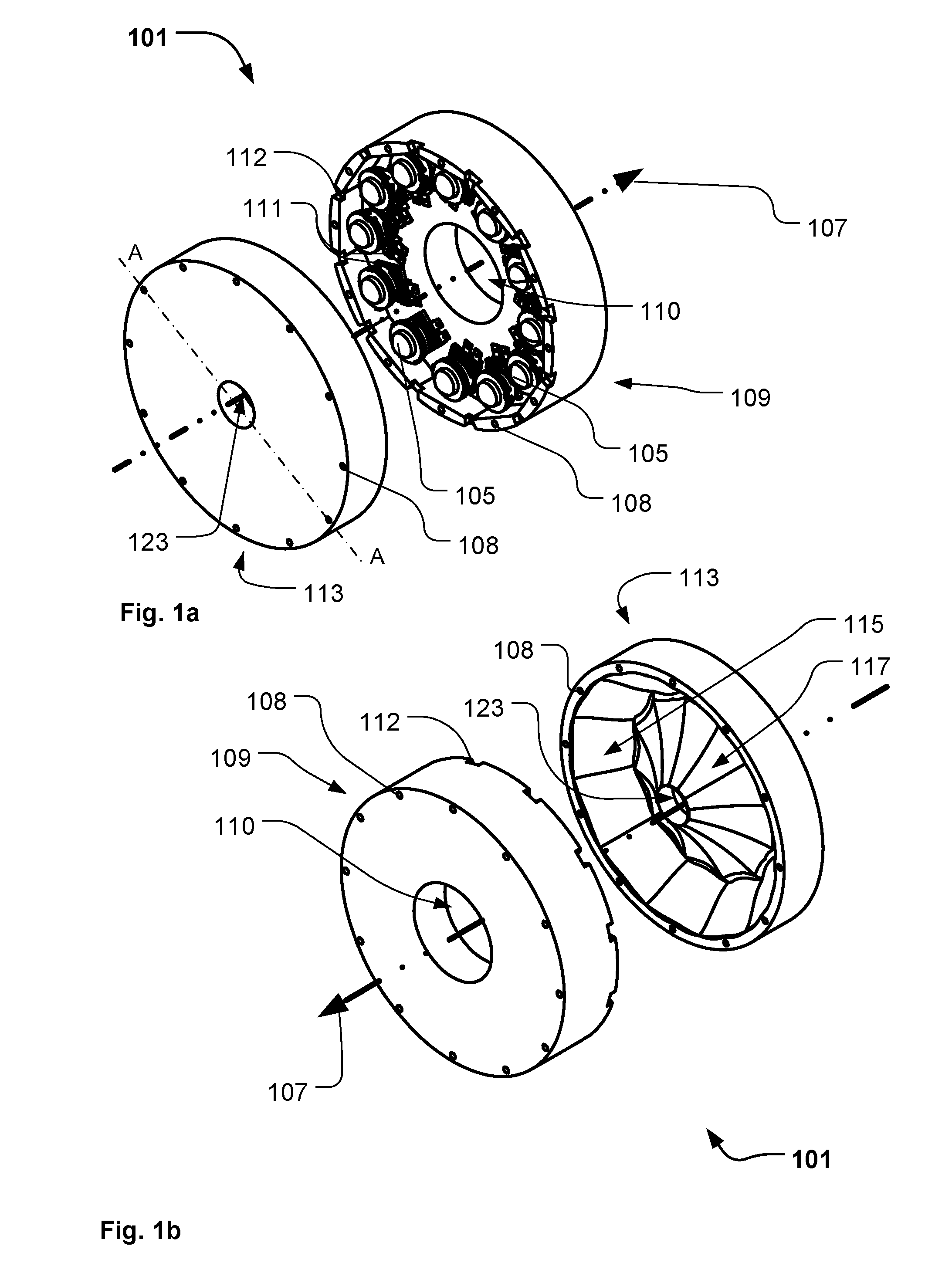
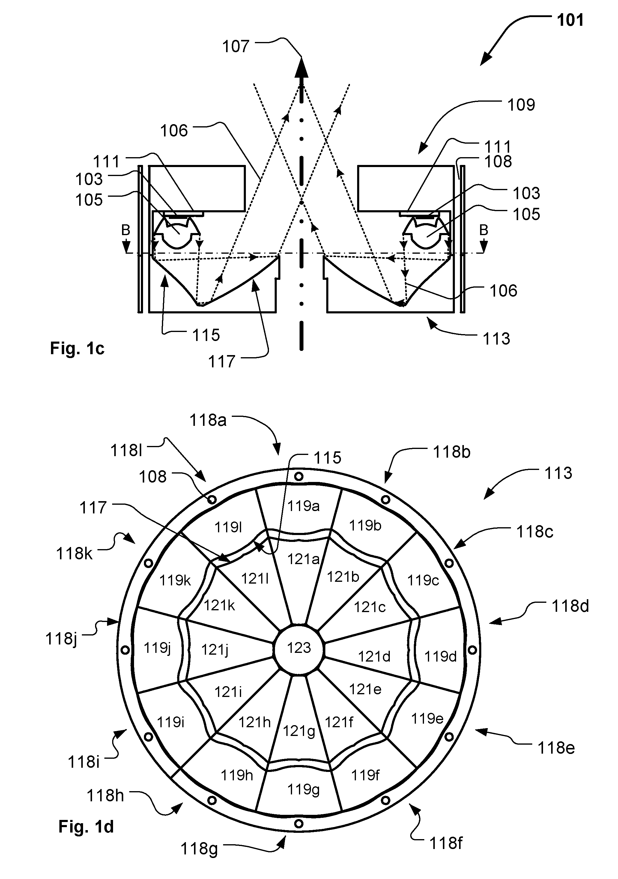
[0018]FIG. 1a-1d illustrate an embodiment of a illumination module according to the present invention;

[0019]FIGS. 2a and 2b illustrate an embodiment of an illumination device according to the present invention;

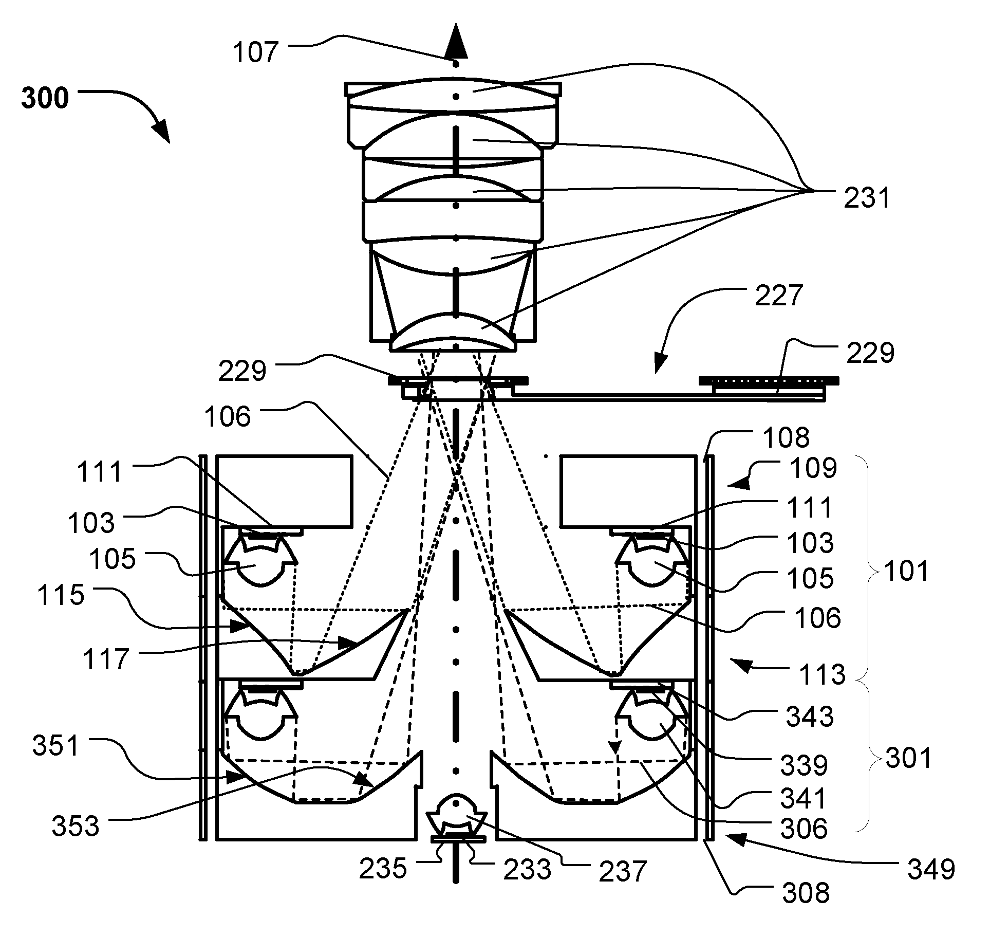
[0020]FIGS. 3a and 3b illustrate an embodiment of an illumination device according to the present invention comprising a first and second illumination module;

[0021]FIG. 4 illustrates simplified illumination device according to the present invention and shows possible design parameters;

[0022]FIG. 5 illustrates a perspective vie...


PUM


Abstract

The present invention relates to a light collector for an illumination device collecting light from a plurality of light sources and combing the collected light into a common light beam, where the common light beam is coupled through an optical gate. The light sources are distributed offset and around an optical axis and the light beam collector comprises a first reflector surrounding the optical axis and a second reflector surrounding the optical axis, where the first reflector reflects the sources light beams towards the second reflector and where the second reflector reflects the source light beams in a direction along the optical axis. The light beam collectors is divided into a number of reflector pairs, where each reflector pair comprises a first surface part of the first reflector and a second surface part of the second reflector, where the second surface part receives light from the corresponding first surface part of the reflector pair.

Description

FIELD OF THE INVENTION[0001]The present invention relates to a light collector for an illumination device collecting light from a plurality of light sources and combing the collected light into a common light beam, and where the common light beam is concentrated through an optical gate.BACKGROUND OF THE INVENTION[0002]In order to create various light effects and mood lighting in connection with concerts, live shows, TV shows, sport events or as a part on architectural installation, light fixtures creating various effects are getting more and more used in the entertainment industry. Typically entertainment light fixtures create a light beam having a beam width and a divergence and can for instance be wash / flood fixtures creating a relatively wide light beam with a uniform light distribution or it can be profile fixtures adapted to project image onto a target surface.[0003]Light emitting diodes (LED) are, due to their relatively low energy consumption, high efficiency, long lifetime, ...

Claims


Application Information

Patent Timeline
IPC IPC(8): F21V7/00
CPCF21V7/0066F21V7/09F21S10/007F21V5/008F21V5/048F21V7/0016F21V7/0058F21V13/04F21W2131/406F21Y2105/00F21Y2115/30F21Y2115/15F21Y2113/20F21Y2115/10
Inventor GADEGAARD, JESPERJENSEN, THOGER
Owner MARTIN PROFESSIONAL
Why Eureka
Eureka Blog
Learn More