Full-field injection atomization measurement device and method based on photon time domain filter technique

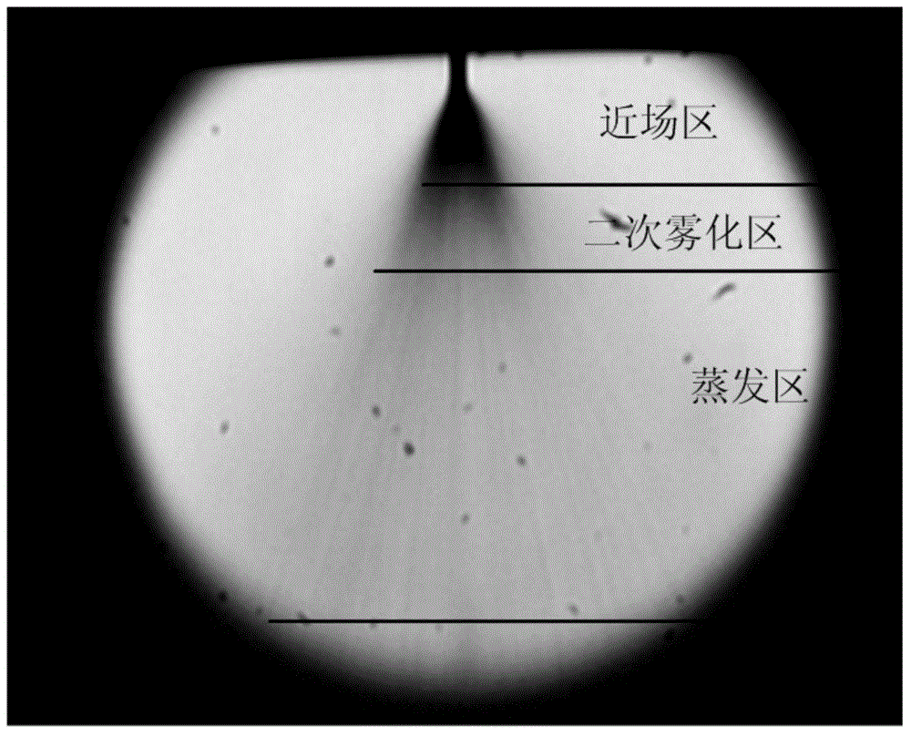
A time-domain filtering and measuring device technology, applied in the field of laser metrology, can solve the problem that the difference in optical transmittance is too large, and it is impossible to obtain the full-field transient structure, near-field area and other area flow fields of the spray atomization process at the same time. The structure is not related, etc.

Active Publication Date: 2015-09-09
HARBIN INST OF TECH
View PDF5 Cites 8 Cited by
  • Summary
  • Abstract
  • Description
  • Claims
  • Application Information

AI Technical Summary

Problems solved by technology

Due to the above reasons, there are currently two difficulties in fog measurement. First, for the near-field region, the optical transmittance difference between the center and edge of the spray region is about 10. 2 ~10 5 times, so it is difficult to obtain a clear full-field structure map of the near-field region at the same time during the measurement
Second, due to the large difference in optical transmittance between the near-field area and other areas, the same measur...

Method used


Image

  • Full-field injection atomization measurement device and method based on photon time domain filter technique
  • Full-field injection atomization measurement device and method based on photon time domain filter technique
  • Full-field injection atomization measurement device and method based on photon time domain filter technique

Examples


specific Embodiment approach 1

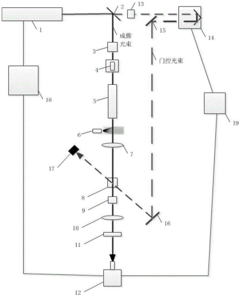
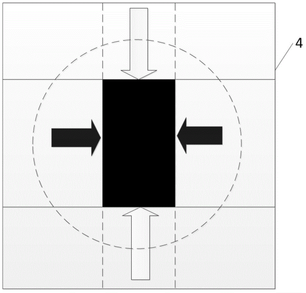
[0026] Specific implementation mode one: as figure 2 , image 3 and Figure 4 As shown, the injection atomization full-field measurement device based on photon time-domain filtering technology provided by this embodiment consists of a femtosecond laser 1, a beam splitter 2, a polarizer 3, a variable rectangular diaphragm 4, and a beam expander system 5 , target injector 6, first convex lens 7, optical Kerr medium 8, analyzer 9, second convex lens 10, attenuator 11 with variable transmittance and its spatial distribution structure, ICOMS camera 12, half-wave plate 13. An optical path delayer 14, a first reflector 15, a second reflector 16, a beam collector 17, a timing control system 18 and a computer 19 are formed.

[0027] The femtosecond laser output by the femtosecond laser 1 is divided into two beams by the beam splitter 2, which are respectively used as the imaging beam and the gating beam, and the gating beam passes through the half-wave plate 13, the optical path del...

specific Embodiment approach 2

[0038] Embodiment 2: In this embodiment, the device described in Embodiment 1 can simultaneously acquire the transient full-field image of the spray field, which is realized by the following steps:

[0039] Step 1: using a femtosecond laser to output 800nm ​​femtosecond laser.

[0040] Step 2: Use a beam splitter to split the femtosecond laser into two beams at a ratio of 1:1, which are respectively used as an imaging beam and a gating beam. The imaging beam is used for spray field imaging, and the gating beam is used to trigger the optical Kerr gate.

[0041] Step 3: The gated light beam sequentially passes through the half-wave plate 13 , the optical path delayer 14 , the first mirror 15 , the second mirror 16 and the optical Kerr medium 8 , and finally reaches the beam collector 17 . The half-wave plate 13 is used to change the deflection direction of the gated beam to ensure that the deflected direction of the gated beam and the imaging beam is at an angle of 45°; the opti...


PUM

PropertyMeasurementUnit
Wavelengthaaaaaaaaaa
Pulse widthaaaaaaaaaa
Thicknessaaaaaaaaaa

Abstract

The invention discloses a full-field injection atomization measurement device and method based on a photon time domain filter technique. The device comprises a femtosecond laser, a beam splitter, a polarizer, a variable rectangular aperture, a beam expanding system, a target injector, a first convex lens, an optical kerr medium, a polarization analyzer, a second convex lens, a transmittance and spatial distribution structure variable attenuator, a ICOMS (Intensified Complementary Metal Oxide Semiconductor) camera, a half wavelength plate, an optical path time delayer, a first reflecting mirror, a second reflecting mirror, an optical beam collector, a sequential control system and a computer. Ballistic photons are selected according to an optical kerr effect for imaging, and a clear spray field structure picture is further acquired; the optical beam is reshaped to rectangular light spots with variable length-width ratios by adopting the variable rectangular aperture and the beam expanding system, and all the spray field is effectively covered; the density of ballistic photons entering a near field region of the ICOMS camera is identical to that of the ballistic photons entering other regions due to the adoption of the transmittance and spatial distribution structure variable attenuator, so that a clear full-field image of the spray field is acquired.

Description

technical field [0001] The invention belongs to the field of laser measurement, and relates to a full-field measurement device and method for injection atomization of an engine injector based on photon time-domain filtering technology. Background technique [0002] Liquid fuel (hydrocarbon) has the advantages of easy storage, portability, high density, high calorific value per unit volume, and practical application. It is widely used in ramjet engines, turbine engines, detonation engines, rocket engines, and automobile engines. The injection and atomization process of engine liquid fuel plays a key role in the entire engine working process, and has a very significant impact on engine combustion efficiency, ignition performance and combustion stability. In addition, the design technology of modern engines mainly uses computational fluid dynamics (CFD), but due to the complexity of the combustion process and the lack of experimental data, the CFD model has many shortcomings, o...

Claims


Application Information

Patent Timeline
IPC IPC(8): G01N15/00
Inventor 彭江波于欣董志伟马欲飞杨振杨超博李晓晖樊荣伟宋梦龙
Owner HARBIN INST OF TECH
Why Eureka
Try Eureka