Device for a motor vehicle, comprising a rotatably mounted camera unit

a camera unit and motor vehicle technology, applied in the field of motor vehicles, can solve the problems of easy vandalism of the camera, easy faults of the direct mounting of the camera on the protective element, and easy exposure of the camera to dirt and moisture burdens, and achieve the effect of increasing the functionality

Inactive Publication Date: 2011-02-22
HUF HULSBECK & FURST GMBH & CO KG
View PDF12 Cites 35 Cited by
  • Summary
  • Abstract
  • Description
  • Claims
  • Application Information

AI Technical Summary

Benefits of technology

The present invention creates a device for a motor vehicle having a rotatably mounted camera unit, which avoids the above-mentioned disadvantages, in particular having a greater functionality which allows effective protection of the camera unit without restricting the quality of the images recorded.
With the inventive device, the camera unit is mounted on the vehicle and is in a protected position in its resting position. Even when the protective element is moved from its closed position into its open position, the camera unit initially remains in its resting position. In a defined open position of the protective element, the mechanism moves the camera unit with a time lag into the active position in which the camera unit can be used for recording images. Through intentional separation of the motion sequences of the protective element and the camera unit, the two moving elements are effectively prevented from colliding. Only when the protective element is in a defined open position is the camera pivoted outward. It is also advantageous that malicious opening of the protective element does not lead to any movement of the camera out of its protected resting position, so that damage to the camera unit can be effectively prevented.
In a preferred embodiment of the present invention, the coupling element is situated on the driven element in such a way that by manual movement of the protective element from the closed position into the open position, the driven element is uncoupled from the coupling element without initiating a movement of the coupling element. This effectively prevents the camera unit from being moved outward by malicious opening of the protective element at the same time.
According to another measure which increases the functionality, the mechanism is arranged within a housing unit in which a lock cylinder for a lock of a locking device is rotatably mounted, whereby the lock cylinder is completely covered in the closed position of the protective element. The inventive device may thus also be used for a moving part of a motor vehicle, in particular a door, a tailgate, a trunk lid or the like within the context of a mechanical emergency unlocking operation. The lock cylinder is in the normal situation effectively covered by the protective element. If the locking device, e.g., the central lock system has failed, access to the lock cylinder is possible for the user by manual opening of the protective element. Because of the inventive mechanism, however, the camera unit is not pivoted out of its resting position by manual opening of the protective element. Manual opening of the lock can be induced by operation of the lock cylinder.

Problems solved by technology

It has been found to be a disadvantage that direct mounting of the camera on the protective element is susceptible to faults.
Due to the effects of weather and wear phenomena, the protective element no longer forms a satisfactory seal after a certain period of time, so that the camera mounted on the protective element is exposed to certain dirt and moisture burdens.
Furthermore, because of its arrangement the camera is easily vandalized, e.g., by destroying the protective element.

Method used


Image

  • Device for a motor vehicle, comprising a rotatably mounted camera unit
  • Device for a motor vehicle, comprising a rotatably mounted camera unit
  • Device for a motor vehicle, comprising a rotatably mounted camera unit

Examples


Embodiment Construction

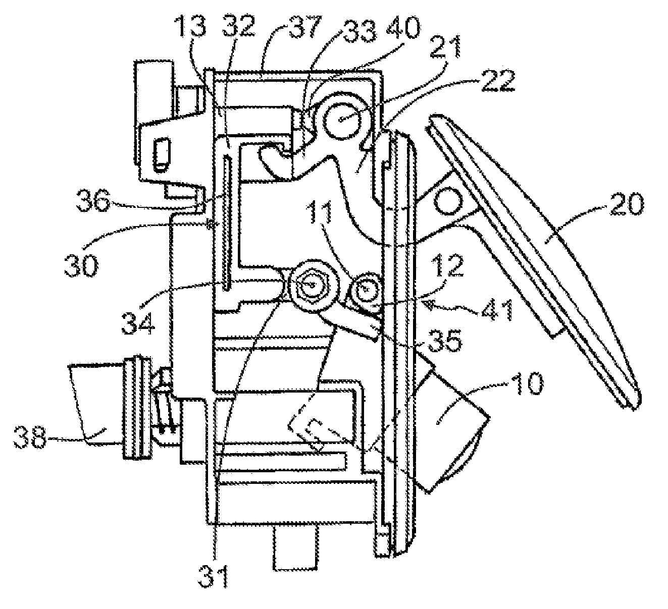
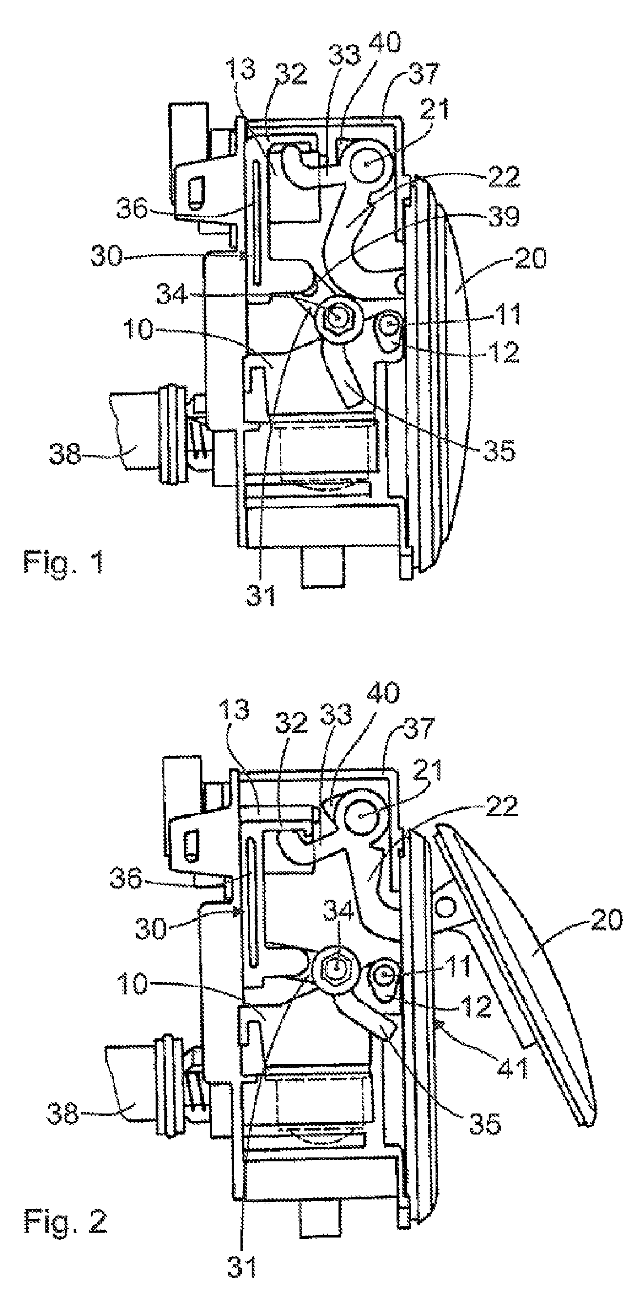
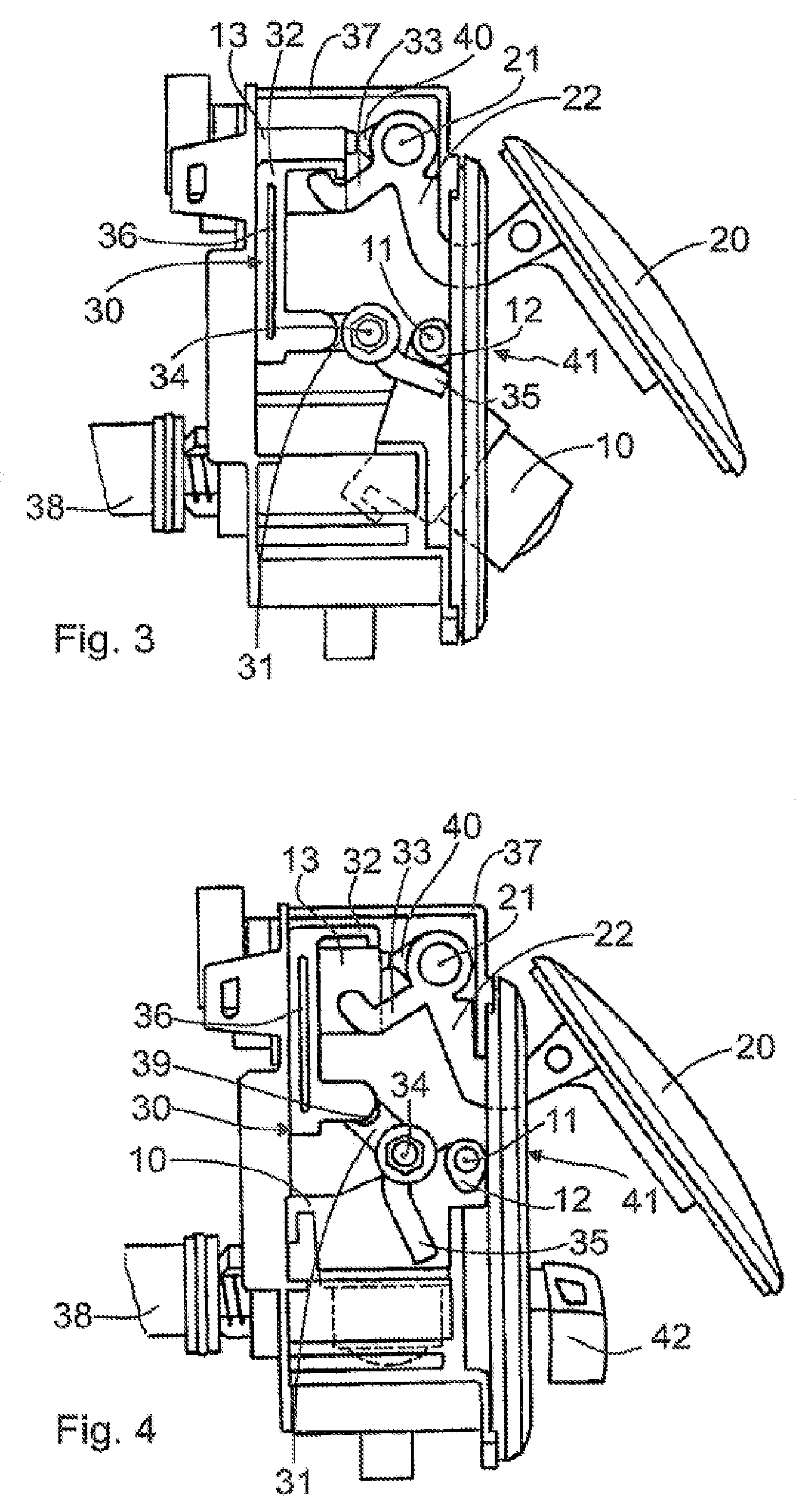
FIGS. 1 to 4 show a possible embodiment of the inventive device for a motor vehicle with a rotatably mounted camera unit 10. The camera unit 10 can be brought into a resting position (see FIG. 1, FIG. 2 and FIG. 4) and into an active position (see FIG. 3) by means of a motor (not shown). In addition, the device has a protective element 20 in the form of a cover, which is rotatably movable about an axle 21. In FIG. 1 the protective element 20, is in a closed position. In the other diagrams, the protective element 20 is an open position.

The camera unit 10 is inside a housing unit 37 and can be moved out of the resting position into the active position about a second axle 11, which is arranged at a distance from the first axle 21. According to the invention, the protective element 20 is connected to the first axle 21 by a curved pivot arm 22. Furthermore, a mechanism 30 which can be driven by the motor and is connected mechanically to the protective element 20 and also to the camera un...


PUM


Abstract

The invention relates to a device for a motor vehicle, comprising a rotatably mounted camera unit (10) which can be brought into an inactive position and into an active position by means of a motor, and a protective element (20) that can be rotatably guided about a first axis (21) into a closed position and into an open position, the camera unit (10), in the closed position, being in its inactive position behind the protective element (20) and inaccessible from the exterior, and, in the open position of the protective element (20), the camera unit (10) assuming the active position for recording images. The invention is characterized in that the camera unit (10) can be displaced from the inactive position into the active position about a second axis (11), arranged at a distance to the first axis (21), the protective element (20) is connected to the first axis (21) via a swivel arm (22), and the motor drives a mechanism (30), mounted on the motor vehicle, which is mechanically connected both to the protective element (20) and to the camera unit (10). The mechanism (30) is configured in such a manner that the camera unit (10) is decoupled from the mechanism when it is in the operating state and that the protective element (20) can be displaced from the closed position to the open position, the camera unit (10) remaining in the inactive position.

Description

FIELD OF THE INVENTIONThe invention relates to a device for a motor vehicle, having a rotatably mounted camera unit, which can brought into a resting position and into an active position by a motor, and having a protective element that is guidable into a closed position and into an open position by rotation about a first axle, such that in the closed position the camera unit is in its resting position behind the protective element, where it is inaccessible from the outside, and in the open position of the protective element the camera unit can be moved into its active position for recording images.BACKGROUND OF THE INVENTIONThe use of cameras for vehicle environment detection is known. Such cameras are used, for example, as parking aids and / or maneuvering aids for motor vehicles to detect the areas that cannot be observed using conventional mirrors in particular.EP 1 529 688 A1 discloses a camera arrangement for motor vehicles having a camera unit for recording images, whereby the c...

Claims


Application Information

Patent Timeline
Patent Type & Authority Patents(United States)
IPC IPC(8): G03B17/00
CPCB60R11/04E05B81/76H04N5/247B60R2011/0082B60R2011/0084B60R2011/0085B60R2011/0092B60R2011/0094E05B81/90E05B83/16E05B85/107H04N23/90
Inventor SCHUETZ, HEIKO
Owner HUF HULSBECK & FURST GMBH & CO KG
Why Eureka
Try Eureka