Planar beam dump

a beam dump and beam technology, applied in the field of system for the capture of energy, can solve the problems of eye injury, damage to surrounding hardware, and relatively heavy dump of copper beams, and achieve the effect of improving the efficiency of airborne applications, and improving the accuracy of airborne applications

Inactive Publication Date: 2011-07-05
THE BOEING CO
View PDF16 Cites 6 Cited by
  • Summary
  • Abstract
  • Description
  • Claims
  • Application Information

AI Technical Summary

Problems solved by technology

Yet another instance during operation when the laser beam is inadvertently directed off the workpiece, such as when one or more of the beam relay optics malfunctions or is miscontrolled.
Because laser beams can injure eyes and damage surrounding hardware during such periods, they must be captured and appropriately terminated in a beam dump.
The resulting weight of the required amount of copper and cooling apparatus makes copper beam dumps relatively heavy, making their use in airborne applications problematic.
Moreover, the housing must be made long in length to reduce the intensity of the beam on the walls of the same, resulting in beam dumps being relatively large in size and their use in airborne applications challenging.
In addition, such conventional beam dumps are difficult and expensive to fabricate.
Moreover, diffuse backscatter of laser energy from conventional beam dump surfaces is also problematic, especially in low power applications where the signal-to-noise ratio in associated detectors is especially critical.

Method used


Image

  • Planar beam dump
  • Planar beam dump
  • Planar beam dump

Examples


Embodiment Construction

)

[0016]Reference will now be made in detail to one or more embodiments of the invention. While the invention will be described with respect to these embodiments, it should be understood that the invention is not limited to any particular embodiment. On the contrary, the invention includes alternatives, modifications, and equivalents as may come within the spirit and scope of the appended claims. Furthermore, in the following description, numerous specific details are set forth to provide a thorough understanding of the invention. The invention may be practiced without some or all of these specific details. In other instances, well-known structures and principles of operation have not been described in detail to avoid obscuring the invention.

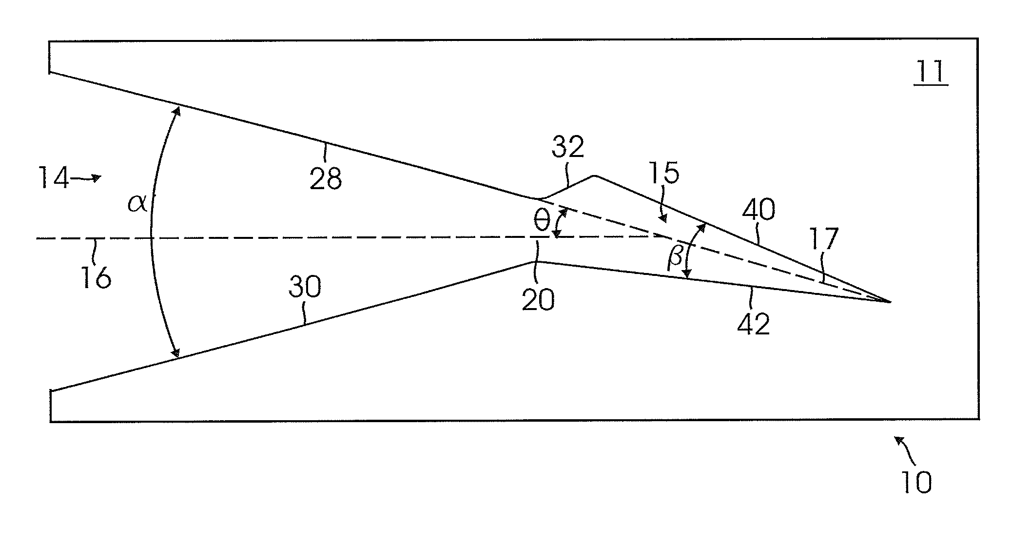
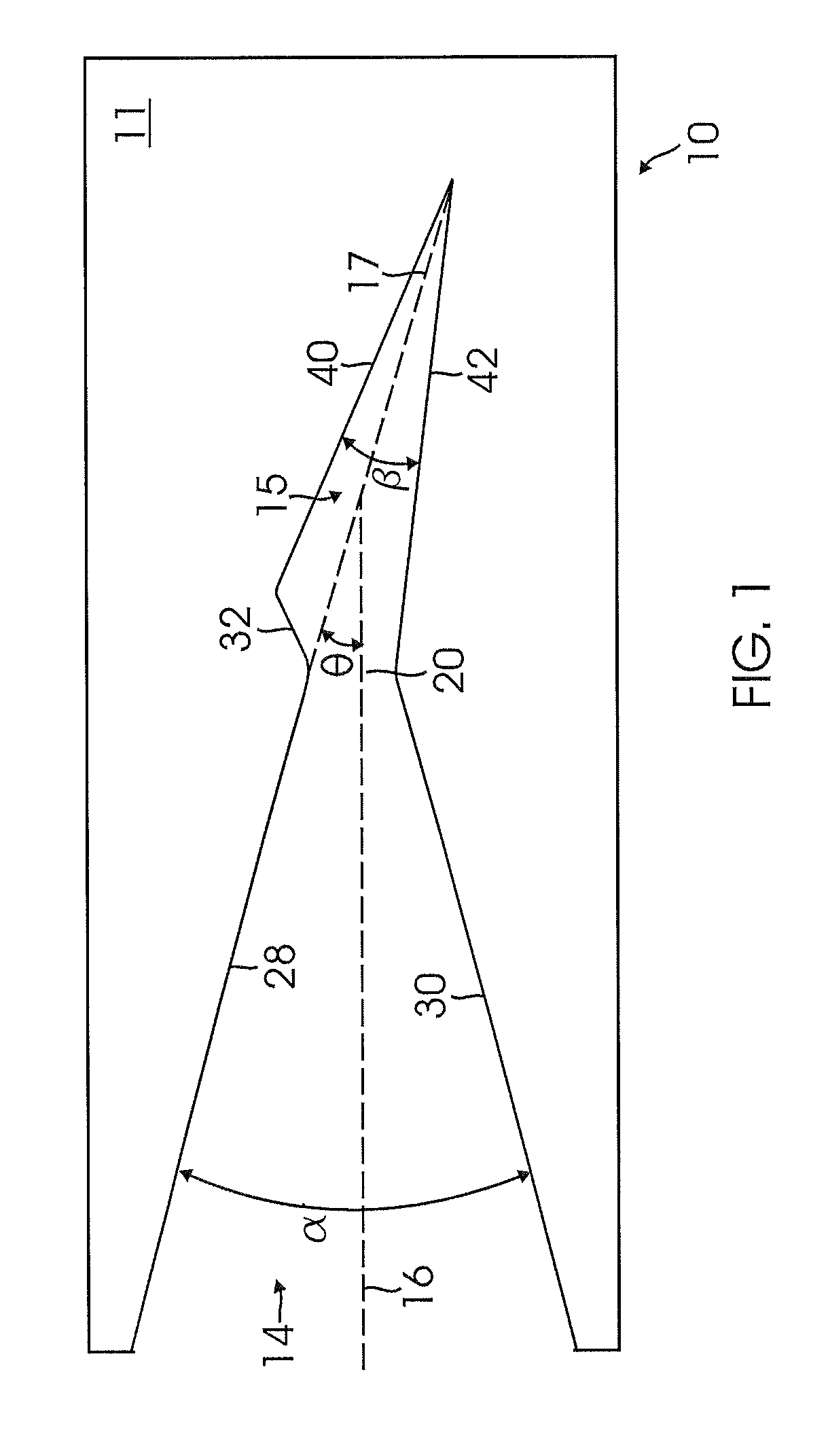
[0017]A beam capture device is provided that exploits the advantageous geometry disclosed in commonly assigned U.S. Pat. No. 7,071,444, the contents of which are incorporated by reference in their entirety. FIG. 1 shows a side view of an exemplar...


PUM

PropertyMeasurementUnit
surface temperaturesaaaaaaaaaa
angleaaaaaaaaaa
energyaaaaaaaaaa

Abstract

In one embodiment, a device for capturing radiation includes: a panel defining a plurality of double wedge chambers, wherein each double wedge chamber includes a first wedge-shaped chamber that tapers into an opening for a second wedge-shaped chamber, and wherein a longitudinal axis of the first wedge-shaped chamber is not collinear with a longitudinal axis of the second wedge-shaped chamber.

Description

CROSS REFERENCE[0001]This patent application is a Divisional patent application of U.S. application Ser. No. 11 / 549,915, filed Oct. 16, 2006.STATEMENT REGARDING FEDERALLY SPONSORED RESEARCH OR DEVELOPMENT[0002]This invention was made with Government support under contract number USZA22-02-C-0049. The Government has certain rights in this invention.TECHNICAL FIELD[0003]The present invention relates generally to systems for the capture of energy such as laser energy.BACKGROUND OF THE INVENTION[0004]While in use, a laser beam is directed at the desired workpiece. For example, in the field of laser welding, the workpiece would be the material being welded. There are periods, however, when laser beams are activated but are not directed at the workpiece, such as during laser beam alignment. There are also instances during operation when a portion of a laser beam is not directed toward the workpiece, such as occurs when a beam splitter in the system creates secondary reflections. A portion...

Claims


Application Information

Patent Timeline
Patent Type & Authority Patents(United States)
IPC IPC(8): B21C25/08
CPCB23K26/425G02B5/003H01S3/005B23K26/704
Inventor EIGLER, LYNNE C.TAM, YAN S.
Owner THE BOEING CO
Why Eureka
Try Eureka