Ion implanters

a technology of ion implants and components, applied in the field of components of ion implants, can solve the problems of sputtering of materials, preventing implantation of wafers, and requiring care, so as to reduce the energy of ions, the effect of reducing energy

Inactive Publication Date: 2009-07-09
APPLIED MATERIALS INC
View PDF7 Cites 8 Cited by
  • Summary
  • Abstract
  • Description
  • Claims
  • Application Information

AI Technical Summary

Benefits of technology

[0013]Biasing the surface in this way is advantageous in that it reduces the energy of the ions before they strike the internal surface. Thus, with their energy reduced, the ions will pose less of a problem in sputtering material from the surface. Preferably, the power supply apparatus is arranged to bias the internal surface to be at substantially the same potential as the ion beam.
[0014]The component may further comprise an array of electrodes disposed between the surface and entrance opening. This allows further electrical contro

Problems solved by technology

These ions striking the beam dump may cause sputtering of material.
Care must be taken though, as material sputtered from the beam dump may become entrained within the ion beam and so contaminate the substrate.
For example, instability in the ion beam may require that implantation of a wafer be stopped as quickly as possible.
Such a beam strike of the whole beam is likely to sputter more material.
Although the material can no longer become entrained within the ion beam, there remains

Method used


Image

  • Ion implanters
  • Ion implanters
  • Ion implanters

Examples


Embodiment Construction

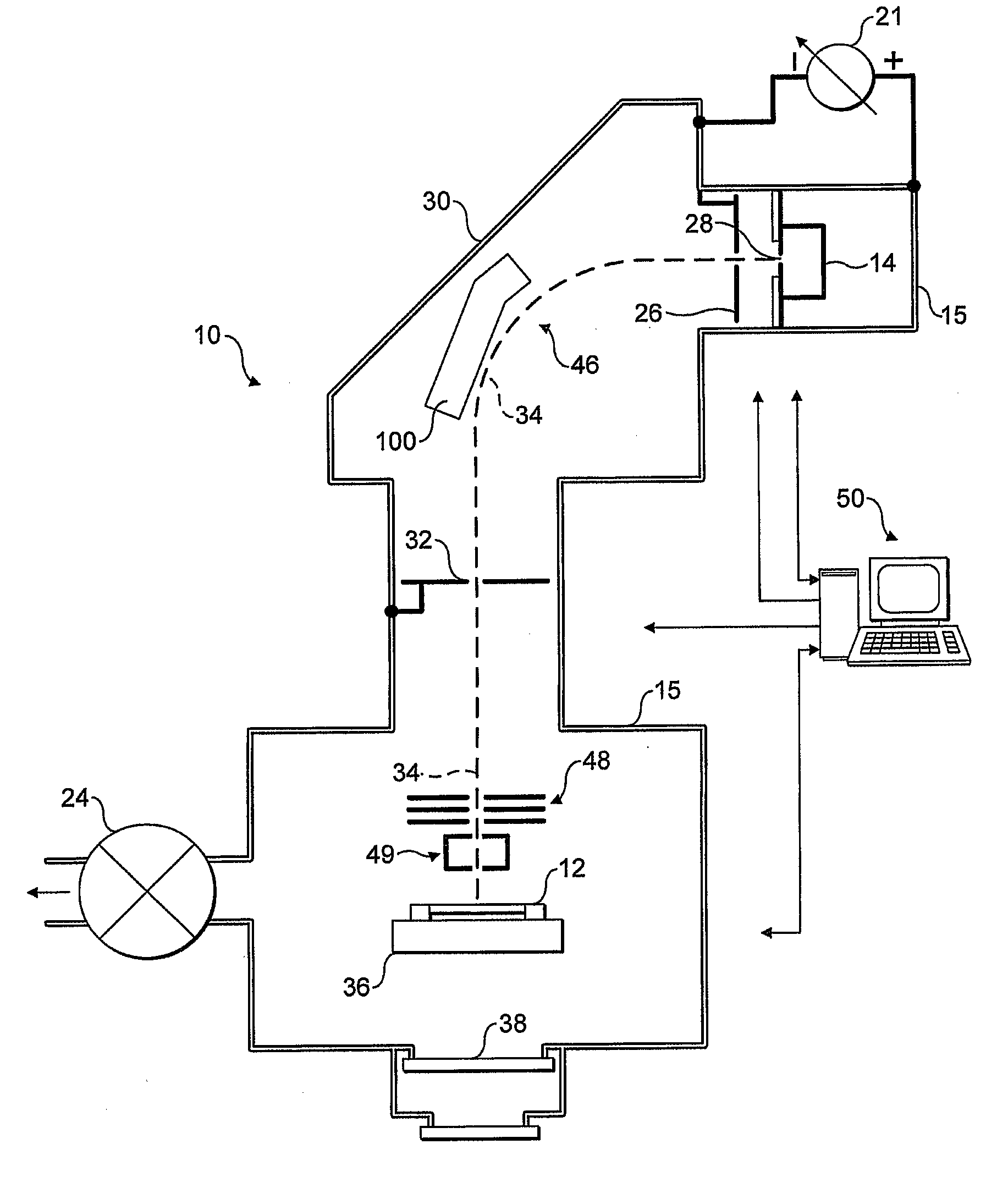
[0025]In order to provide a context for the present invention, an exemplary application is shown in FIG. 1, although it will be appreciated this is merely an example of an application of the present invention and is in no way limiting.

[0026]FIG. 1 shows an ion implanter 10 for implanting ions in semiconductor wafers 12 that may be used in accordance with the present invention. The ion implanter 10 comprises a vacuum chamber 15 pumped through valve 24. Ions are generated by ion source 14 and are extracted by an extraction lens assembly 26 to form an ion beam 34. In this embodiment this ion beam 34 is steered and shaped through the ion implanter 10 such that the ion beam 34 passes through a mass analysis stage 30. Ions of a desired mass are selected to pass through a mass resolving slit 32 and then conveyed onward along an ion beam path 34 towards the semiconductor wafer 12. In this embodiment, the ions are decelerated before reaching the semiconductor wafer 12 by deceleration lens as...


PUM


Abstract

The present invention relates to components in an ion implanter that may see incidence of the ion beam, such as a beam dump or a beam stop. Such components will be prone to the ions sputtering material from their surfaces, and sputtered material may become entrained in the ion beam. This entrained material is a source of contamination. The present invention provides an ion implanter comprising power supply apparatus and an ion-receiving component. The component has an opening that receives ions from an ion beam such that ions strike an internal surface. The power supply apparatus is arranged to provide an electrical bias to the internal surface to decelerate the ions prior to their striking the surface, thereby mitigating the problem of material being sputtered from the surface.

Description

FIELD OF THE INVENTION [0001]The present invention relates to components in an ion implanter that may see incidence of the ion beam, such as a beam dump or a beam stop.BACKGROUND OF THE INVENTION [0002]Ion implanters are used in the manufacture of semiconductor devices and other materials. In such ion implanters, semiconductor wafers or other substrates are modified by implanting atoms of a desired species into the body of the wafer, for example to form regions of varying conductivity.[0003]Ion implanters are well known and generally conform to a common design as follows. An ion source generally comprises an arc chamber in which a hot plasma is generated. The plasma will contain ions of a desired species to be implanted.[0004]An extraction lens assembly produces an electric field that extracts ions from the ion source and forms a mixed beam of ions. Only ions of a particular species are usually required for implantation in a wafer or other substrate, for example a particular dopant ...

Claims


Application Information

Patent Timeline
IPC IPC(8): G21K5/00
CPCH01J37/04H01J37/3171H01J2237/04756H01J2237/022H01J2237/0213
Inventor ALCOTT, GREGORY ROBERTMURRELL, ADRIAN
Owner APPLIED MATERIALS INC
Why Eureka
Try Eureka