Thermally Insulating Member

a technology of thermal insulation and member, applied in the direction of thin material processing, domestic cooling apparatus, packaging, etc., to achieve the effect of high cost in us

Active Publication Date: 2014-11-06
BETTER ALLYING DESIGN
View PDF0 Cites 8 Cited by
  • Summary
  • Abstract
  • Description
  • Claims
  • Application Information

AI Technical Summary

Benefits of technology

[0010]The primary objective of the present invention is to provide a thermally insulating member to overcome the disadvantages of insufficient thermally insulating effect and high costs in use of the conventional thermally insulating member.
[0011]The present invention fulfills the above objective by providing a thermally insulating member including a plane sheet having two ends spaced from each other in a length direction and two sides spaced from each other in a thickness direction perpendicular to the length direction and extending between the ends. The plane sheet includes a plurality of rows of slits between the ends of the plane sheet. Each of the plurality of rows of slits extends from one of the two sides through the other side of the plane sheet. Two adjacent rows of slits are spaced from each other in the length direction by a first spacing. Two adjacent slits in the same row of slits are spaced from each other in a width direction perpendicular to the length and width directions by a second spacing. The first spacing is larger than the second spacing. A thermally insulating strip is defined between two adjacent rows of slits. A stretchable rib is formed between two adjacent slits in the same row of slits. Each end of the plane sheet is a coupling portion free of the slits. The effect achieved by the above technical solution is that when the thermally insulating member is stretched outward, due to the action of the stretchable ribs of the thermally insulating member, the originally plane thermally insulating strips twist and become slanted, protrusive, and wavy. After the thermally insulating strips become wavy, substantially rhombic heat dissipating holes are defined by the thermally insulating strips and the stretchable ribs. Thus, each thermally insulating strip is in point contact with the packaging material of the hot food. Namely, the thermally insulating member can form a thermally insulating area by the plurality of rows of slits, the thermally insulating strips, and the stretchable ribs, such that the thermally insulating member possesses an excellent thermally insulating effect to increase the efficacy of the thermally insulating member. Furthermore, a wrapping and tightening effect is provided due to the physical properties of the stretchable ribs, such that the thermally insulating member can tightly abut the object to be thermally insulated with the risk of disengagement.
[0012]Another effect achieved by the above technical solution is that by forming the thermally insulating member with the plane sheet, the stacked height of plane sheets is small, effectively reducing the volume and costs for transportation of the thermally insulating members, thereby reducing the use costs of the thermally insulating member.

Problems solved by technology

Furthermore, a wrapping and tightening effect is provided due to the physical properties of the stretchable ribs, such that the thermally insulating member can tightly abut the object to be thermally insulated with the risk of disengagement.

Method used


Image

  • Thermally Insulating Member
  • Thermally Insulating Member
  • Thermally Insulating Member

Examples


Embodiment Construction

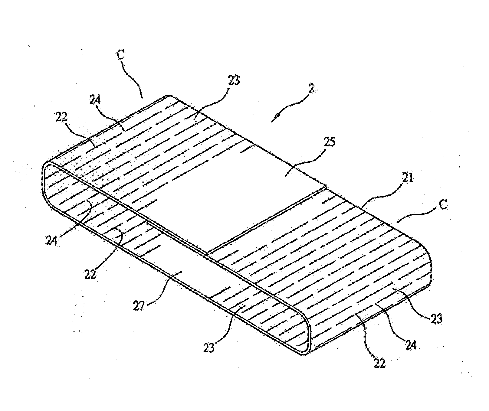
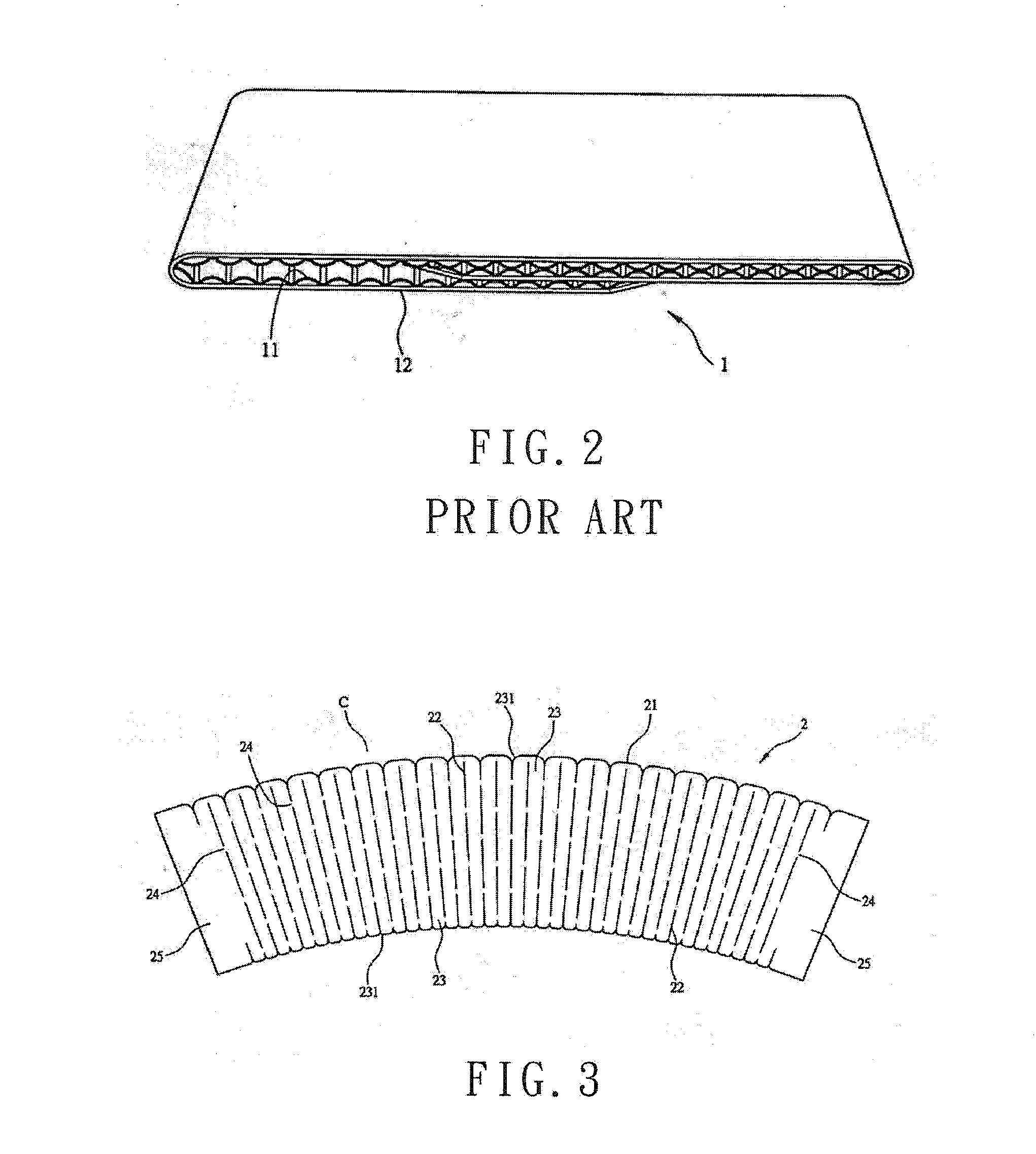
[0024]With reference to FIG. 3, a thermally insulating member 2 according to the present invention is generally made of paper or other tough material. The thermally insulating member 2 includes a plane sheet 21 having two ends spaced from each other in a length direction and two sides spaced from each other in a thickness direction perpendicular to the length direction and extending between the two ends. The plane sheet 21 includes a plurality of rows of slits 22 between the ends of the plane sheet 21. Each row of slits 22 extends from one of the sides through the other side of the plane sheet 21. Two adjacent rows of slits 22 are spaced from each other in the length direction by a first spacing. Two adjacent slits 22 in the same row of slits 22 are spaced from each other in a width direction perpendicular to the length and width directions by a second spacing. The first spacing is larger than the second spacing. A thermally insulating strip 23 is defined between two adjacent rows o...


PUM


Abstract

A thermally insulating member includes a plane sheet having two ends spaced in a length direction and two sides spaced in a thickness direction perpendicular to the length direction. The plane sheet includes a plurality of rows of slits between the ends of the plane sheet. Each row of slits extends from one of the sides through the other side of the plane sheet. A first spacing between two adjacent rows of slits in the length direction is larger than a spacing between two adjacent slits in the same row of slits in a width direction perpendicular to the length and width directions by a second spacing. A thermally insulating strip is defined between two adjacent rows of slits. A stretchable rib is formed between two adjacent slits in the same row of slits. Each end of the plane sheet is a coupling portion free of the slits.

Description

BACKGROUND OF THE INVENTION[0001]1. Field of the Invention[0002]The present invention relates to a thermally insulating member and, more particularly, to a structure of a thermally insulating member providing an excellent thermally insulating effect and using less material for environmental protection as well as greatly reducing the costs for storage and transportation.[0003]2. Description of the Related Art[0004]Persons engaged in the fields of extremely developed industries and businesses must provide the customers with fast and satisfactory commodities or services so as to have a place in the competing markets. With regard to the restaurant business, hot foods to be consumed at certain temperatures, such as coffee, tea, boxed meals, are extremely valued markets by large businesses.[0005]To allow easy carriage and hold of a hot food, a thermally insulating member 1 is generally provided around a packaging material of the hot food. The thermally insulating member 1 avoids the custo...

Claims


Application Information

Patent Timeline
Patent Type & Authority Applications(United States)
IPC IPC(8): B65D81/38
CPCB65D81/3865B65D81/3876A47G23/0216Y10T428/24306Y10T428/24314
Inventor ZHANG, SHAO-WEN
Owner BETTER ALLYING DESIGN
Why Eureka
Try Eureka