Mobile furniture system

a furniture system and mobile technology, applied in the field of furniture systems, can solve the problems of affecting the convenient and safe relocation of the furniture system, the limited use of pallet jacks or forklifts, and the inability to conveniently and safely relocate the typical furniture system

Active Publication Date: 2014-11-13
ROYSTON HAMILTON LLC
View PDF13 Cites 29 Cited by
  • Summary
  • Abstract
  • Description
  • Claims
  • Application Information

AI Technical Summary

Problems solved by technology

Due to their size and weight and because they often support any or all of the above listed equipment, typical furniture systems cannot be conveniently and safely relocated.
In addition, even in situations in which some disassembly is undertaken, typical furniture systems may generally require multiple people to carry the disassembled components to the new location before being reassembled.
While this may be accomplished without initially unloading the above-identified equipment, utilizing a pallet jack or forklift may be limited to locations which are accessible to these machines because pallet jacks and forklifts are often large bulky machines that require significant space within which to maneuver.
As such, space restrictions around the furniture system, such as the presence of other furniture and equipment, may prohibit access via a pallet jack or forklift and thus inhibit convenient relocation of the furniture system.
Furthermore, space restrictions within the facility itself, such as, doorways, stairs, and / or elevators, between the current location of the furniture system and the new location for the furniture system may limit use of pallet jacks and forklifts.
Known mobile furniture systems are generally incapable of carrying sufficient weight and are often prone to tipping when being relocated.
However, a small amount of tilt as the result of being moved along an incline or across a threshold which inadvertently catches one wheel, may cause the system to become unstable, and, absent external application of a force to counteract gravity, inadvertent tilting may have catastrophic consequences and may cause injury and / or destruction of equipment.

Method used


Image

  • Mobile furniture system
  • Mobile furniture system
  • Mobile furniture system

Examples


Embodiment Construction

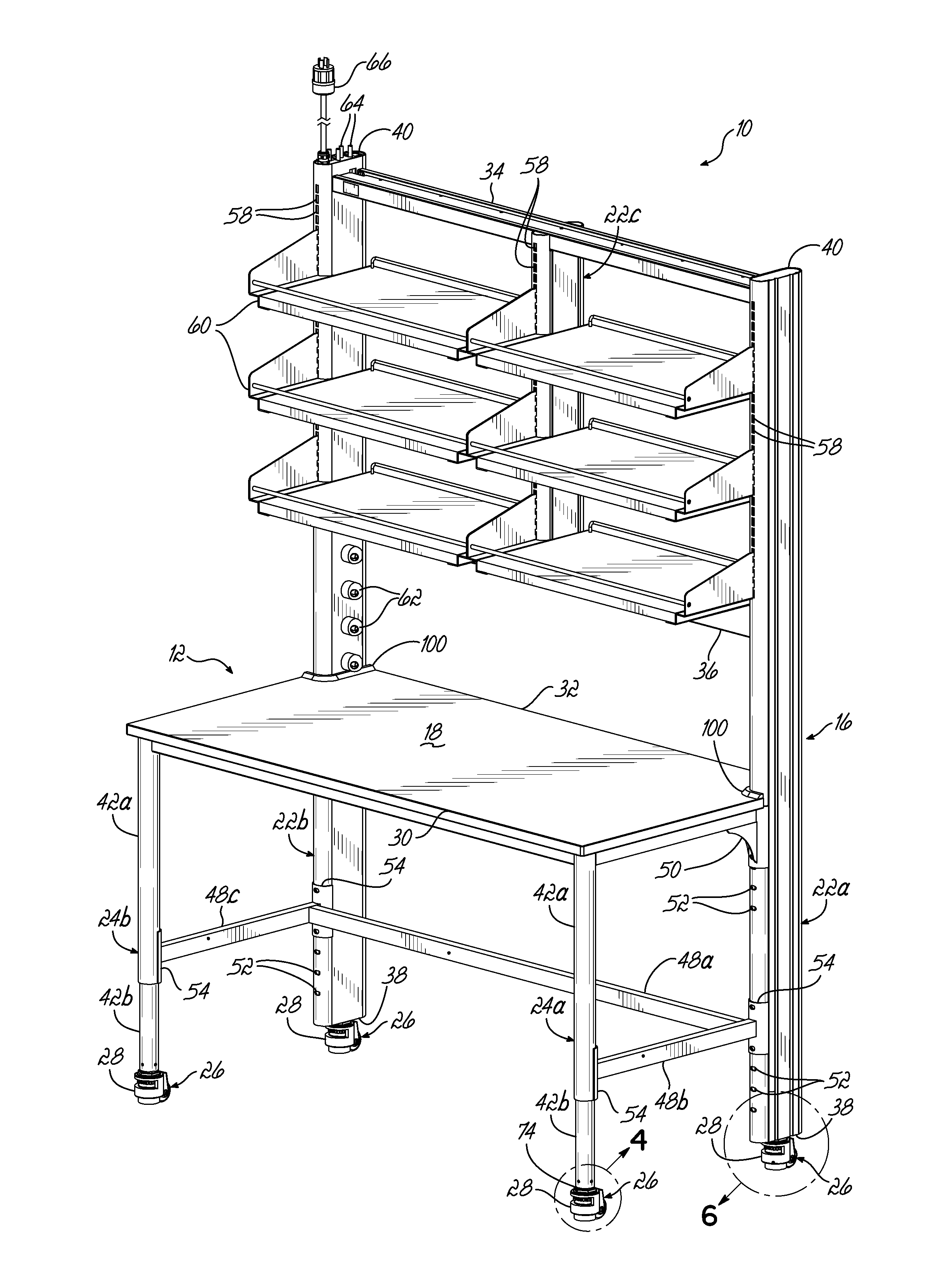
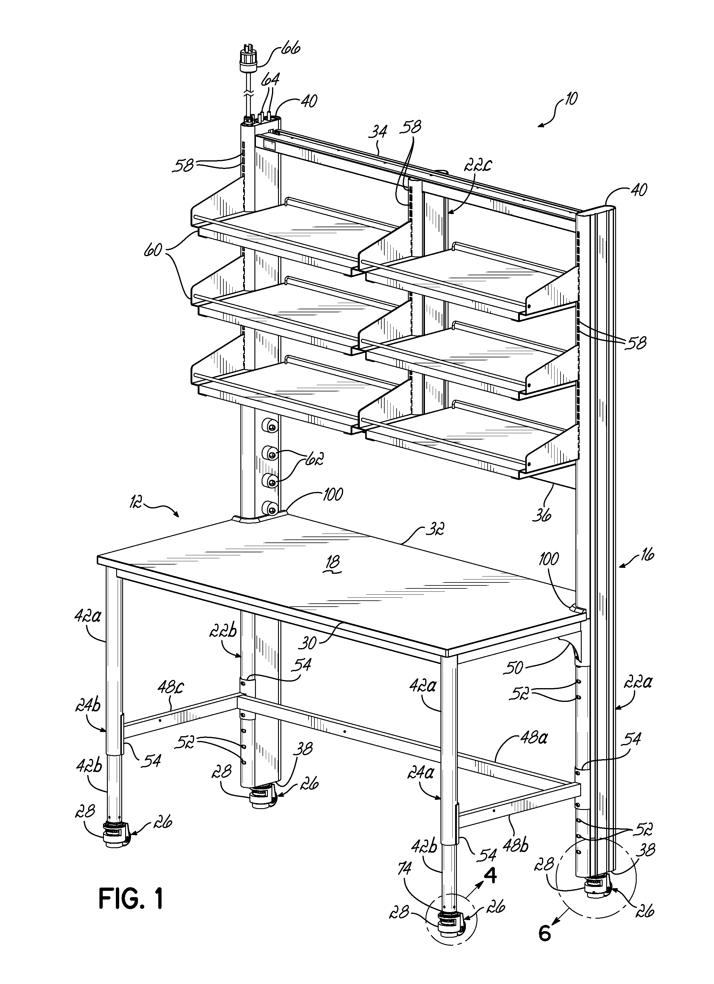
[0032]FIG. 1 depicts an exemplary mobile furniture system 10 in accordance with the principles of the present invention. In one embodiment, the mobile furniture system 10 comprises a mobile laboratory benching system and includes a single-sided workstation 12 supported by a framework assembly 16. The workstation 12 includes a generally planar work surface, or tabletop 18, that is at least partially supported by vertical frame members 22a, 22b of the framework assembly 16. As shown, each vertical frame member 22a and 22b extends above the work surface 18. Leg members 24a, 24b are operatively coupled to the work surface 18, as shown. In the exemplary embodiment shown, the framework assembly 16, for example, the vertical frame members 22a, 22b, and each leg member 24a, 24b are supported on the ground or floor by rotatable supports 26 or feet 28, which are operatively coupled thereto. The rotatable supports 26 are provided to movably support the mobile furniture system 10 when it is des...


PUM


Abstract

A mobile furniture system includes a work surface and a framework assembly, which includes a pair of vertical frame members to support the work surface. The frame members extend above the work surface. At least one utility service line is routed through the framework assembly. A rotatable support may be operatively coupled to each frame member. The rotatable support includes a housing and a rotatable wheel. At least a portion of each of the rotatable supports is in vertical alignment with one frame member. A pair of leg members is operatively coupled to the work surface and is spaced from the pair of frame members. Another rotatable support is coupled to each leg member. A movable foot may be coupled to each of the frame members and to each of the leg members to support the system in a stationary configuration upon a lowering movement of the movable foot.

Description

CROSS-REFERENCE[0001]This application claims priority to U.S. Provisional Patent Application Ser. No. 61 / 821,467 filed May 9, 2013 (Pending), the disclosure of which is incorporated by reference herein in its entirety.FIELD OF THE INVENTION[0002]The present invention relates generally to furniture systems and, more particularly, to mobile furniture systems suitable for use in various laboratory and other environments.BACKGROUND OF THE INVENTION[0003]Furniture systems that can be moved to different locations within a facility are desirable in many applications and environments, such as laboratories, product inspection stations, manufacturing assembly stations, and clean rooms, for example. The mobility of such systems may provide improved flexibility for that environment. Typically, furniture systems include a tabletop, or other generally planar work surface, and may be adapted to support shelving, drawers, dividers, suspended cabinets, tack boards, and various other accessories. Dur...

Claims


Application Information

Patent Timeline
Patent Type & Authority Applications(United States)
IPC IPC(8): A47B21/06A47B37/00A47B13/02
CPCA47B21/06A47B13/02A47B37/00A47B2021/066A47B2037/005B01L9/02B25H1/12
Inventor SEEFELDT, DAVID A.HOLZER, MICHAEL A.HECKER, ROBIN E.
Owner ROYSTON HAMILTON LLC
Why Eureka
Try Eureka