Supercharge Your Innovation With Domain-Expert AI Agents!

Camera flash gun diffuser

a technology of flash gun and diffuser, which is applied in the field of camera flash gun diffuser, can solve the problems of long flash gun recharge period, uncomfortable eye-to-eye brightness, draining battery power, etc., and achieve the effect of reducing shadows and less time-consuming

Inactive Publication Date: 2014-11-13
MO CHAU TONY TING
View PDF1 Cites 1 Cited by
  • Summary
  • Abstract
  • Description
  • Claims
  • Application Information

AI Technical Summary

Benefits of technology

The patent text describes a flash gun that has a light output window angled to the flash gun output, resulting in a forward directed flash. The light is scattered within the enclosure before exiting the window. The flash gun can also be pointed forward, and the adjustment window opened, to provide surrounding illumination and reduce shadows. The technical effect is that the flash gun can provide a forward directed flash while minimizing power consumption. Additionally, the diffuser effect can be turned off by simply opening the window, which is faster than removing the diffuser.

Problems solved by technology

The bright output is often uncomfortable on the eyes for the subject being photographed, and the narrow directional range gives rise to sharp shadowing in the image.
There are different problems associated with the different designs.
This drains battery power and results in a longer flash gun recharge period.
If light is directed only forwards, the problem of shadowing is not addressed.
There is also a problem that a different flash configuration is needed for different surroundings, and applying and removing known diffusers takes time which may result in a photo opportunity being lost.
Existing diffuser designs do not give this flexibility.

Method used


Image

  • Camera flash gun diffuser
  • Camera flash gun diffuser
  • Camera flash gun diffuser

Examples


Embodiment Construction

[0029]The invention provides a camera flash gun diffuser which fits over a camera flash gun. A light input opening over the camera flash gun is angled with respect to a light output window of the diffuser by for example 90 degrees. The inner surface of the casing is reflective so that light is redirected from the flash gun output to the output window. A wall of the casing opposite the flash gun output face comprises an adjustment window that can be opened and closed. This allows direct flash light to escape, for example to provide a controlled amount of upwardly directed general background illumination in addition to the diffused forward directed subject illumination.

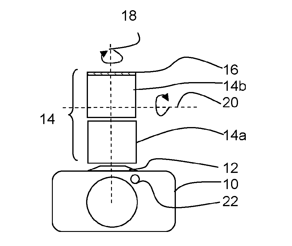
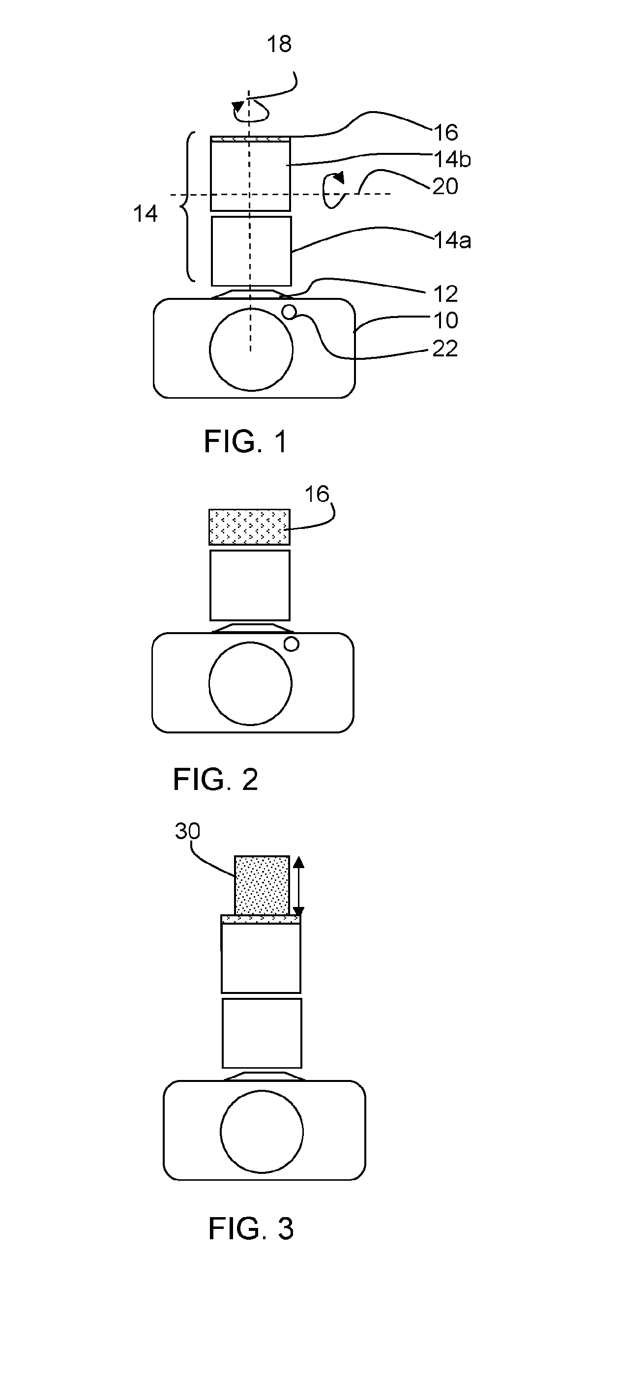
[0030]FIG. 1 shows a known camera with the flash gun facing upwards and shows the adjustments that can be made.

[0031]The camera comprises a camera body 10 with a hotshoe 12 and a flash gun 14. Professional camera flash guns are typically adjustable in the manner shown. The flash gun has a base part 14a for mounting on t...


PUM


Abstract

A camera flash gun diffuser fits over a camera flash gun. A light input opening over the camera flash gun is angled with respect to a light output window of the diffuser. The inner surface of the casing is reflective so that light is redirected from the flash gun output to the output window. A wall of the casing opposite the flash gun output face comprises an adjustment window that can be opened and closed. This allows direct flash light to escape, for example to provide a controlled amount of upwardly directed general background illumination.

Description

FIELD OF THE INVENTION[0001]This invention relates to camera flash gun diffusers.BACKGROUND OF THE INVENTION[0002]A camera flash gun gives out a bright short burst of light from a relatively small area. Generally, the flash gun is pointed forwards at the subject, and the flash gun is not intended to illuminate the whole field of view. The bright output is often uncomfortable on the eyes for the subject being photographed, and the narrow directional range gives rise to sharp shadowing in the image.[0003]It is well known to alleviate these problems by using a diffuser. For example, some camera flash guns have a pull out diffuse reflector. The camera flash gun is pointed upwardly, and part of the light is reflected towards the subject by the diffuse reflector. This reduces the intensity perceived by the subject, and it also enables additional light to flood the scene, for example by reflection from the ceiling in a room. This reduces the harshness of shadows.[0004]There are also many a...

Claims


Application Information

Patent Timeline
Patent Type & Authority Applications(United States)
IPC IPC(8): G03B15/06G03B15/03G02B5/02
CPCG03B15/06G02B5/0294G03B15/03G03B15/05G03B2215/0589
Inventor MO CHAU, TONY TING
Owner MO CHAU TONY TING
Features
  • R&D
  • Intellectual Property
  • Life Sciences
  • Materials
  • Tech Scout
  • Unparalleled Data Quality
  • Higher Quality Content
  • 60% Fewer Hallucinations
Learn More