Shell body joint structure and jointing method thereof

A joint structure and joint method technology, applied in the direction of base/housing, electrical equipment housing/cabinet/drawer, electrical components, etc., can solve the problem of affecting the electrical characteristics of electronic devices or their accessories, electrical leakage, and insufficient creepage distance of electrical clearances And other issues

Active Publication Date: 2004-11-17
DELTA ELECTRONICS INC +1
View PDF0 Cites 17 Cited by
  • Summary
  • Abstract
  • Description
  • Claims
  • Application Information

AI Technical Summary

Problems solved by technology

In addition, when the upper and lower shells 1, 2 are joined, the creepage distance of the electrical gap formed between the joints 11, 12 is still not long enough, so there may be electrical leakage, which indirectly affects the electronic device or its accessories. electrical characteristics

Method used


Image

  • Shell body joint structure and jointing method thereof
  • Shell body joint structure and jointing method thereof
  • Shell body joint structure and jointing method thereof

Examples


Embodiment Construction

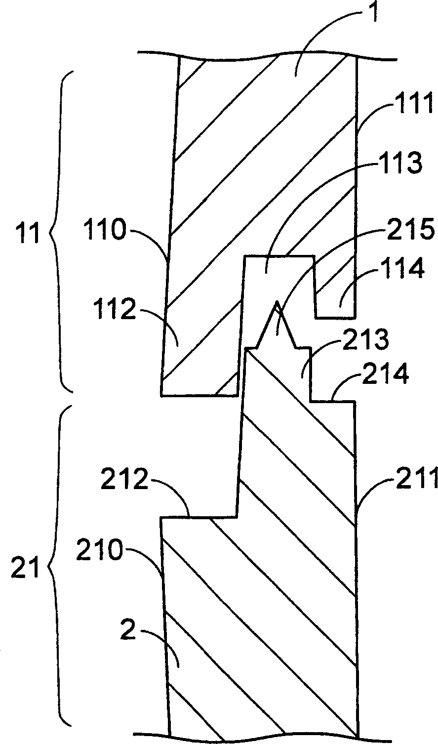
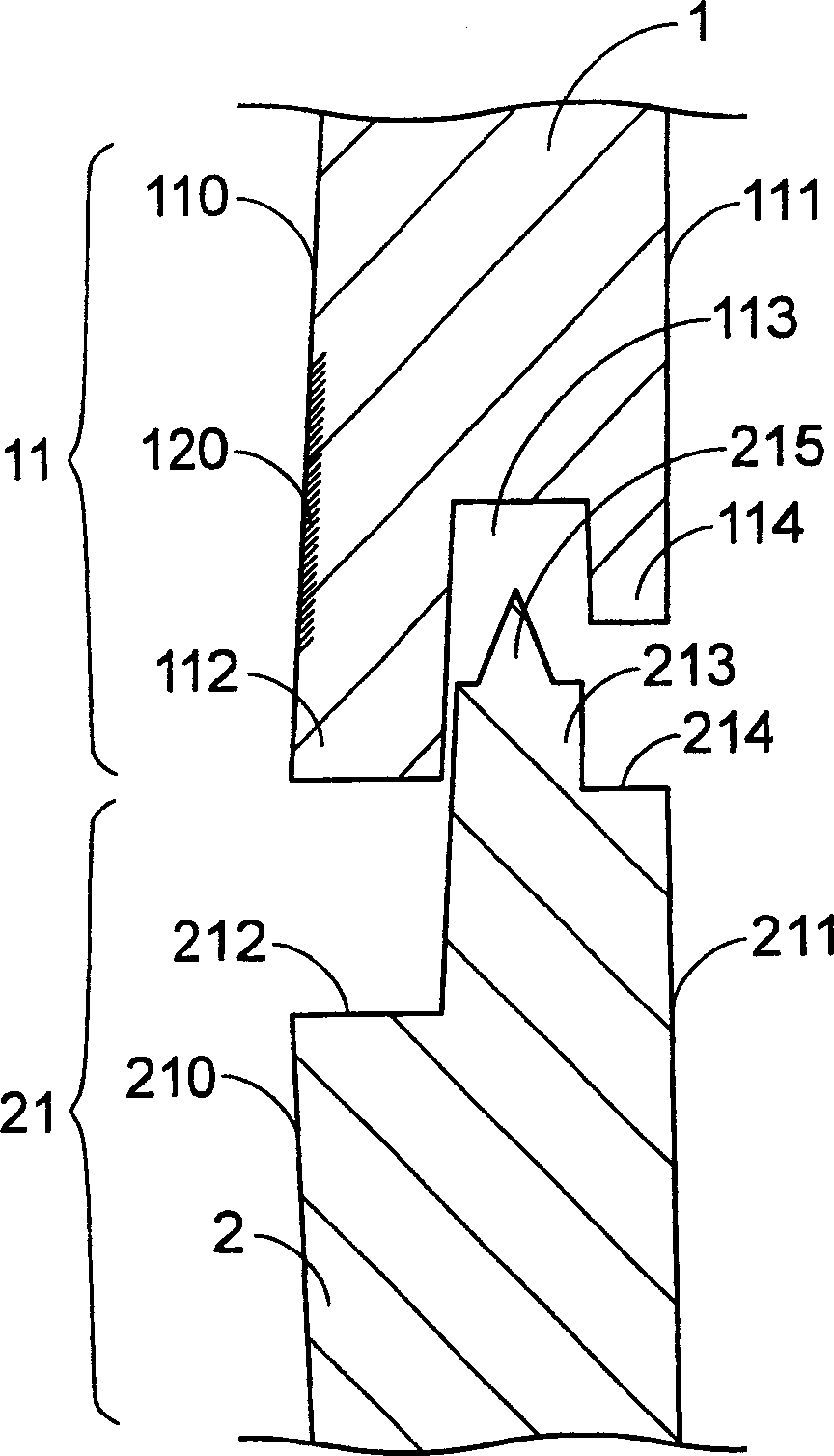
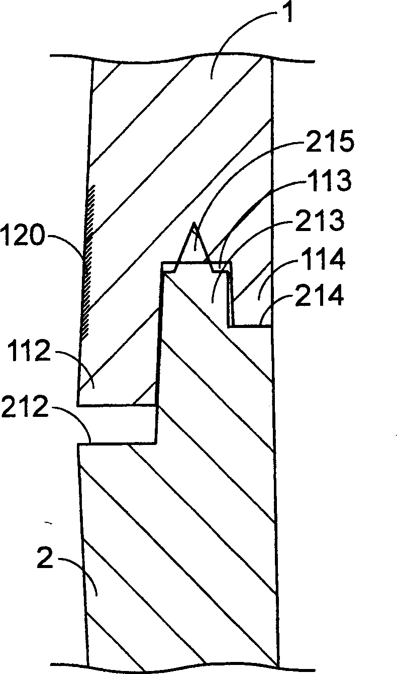
[0046] see image 3 , which is a schematic diagram showing the joint structure of the housing in a preferred embodiment of the present invention. Such as image 3 As shown, the housing joint structure of the present invention is composed of an upper housing 3 and a lower housing 4 engaged with each other. The upper casing 3 has a joint portion 31, which sequentially forms a first concave portion 312, a first convex portion 313, a first groove 314 and a first Two convex parts 315. In addition, the lower case 4 also has a joint portion 41 , and the joint portion 41 forms a first concave portion 412 , a first convex portion 413 and a second concave portion 414 sequentially from the outer surface 410 to the inner surface 411 . In this embodiment, the first concave portion 312 and the first convex portion 313 of the upper case 3 are opposite to the first concave portion 412 of the lower case 4 , and their widths are approximately equal. In addition, the first groove 314 and the...


PUM


Abstract

The invention relates to a kind of shell joint structure and its joint method. The joint structure consists at least two parts: upper shell, which bears a joint including(from its outside to its inside orderly) first concave, first convex, first flute and second convex; and lower shell, which also bears a joint including(from its outside to its inside orderly) first concave, first convex and second concave. In addition, the first concave and the first convex of the upper shell are relative to the first convex of the lower shell, and the first flute and the first convex of the upper shell are relative to the first convex and the second concave of the lower shell respectively, thus jointing the upper shell and the lower one together. Through the use of this type of shell joint structure and its joint method, shell shadow and line flows can be reduced and the increase of the electricity climbing distance of the electric clearance after the combination of the shells will enhance the appearance of the shells of electric devices and their components as well as their electric characteristic.

Description

technical field [0001] The present invention relates to a housing joint structure and its joining method, especially a housing joint that can reduce housing shadows or flow marks and increase electrical clearance creepage distance (creepagedistance) after the housings are combined structure and its joining method. Background technique [0002] In daily life, people often use various electronic devices or their accessories, such as power adapters, connectors, power supplies, plugs or sockets, and so on. Since these electronic devices or their accessories need to properly isolate and protect their internal electronic components or circuits, they all use casings to cover these electronic components and circuits to avoid direct contact with the outside world. Since the shell joint structure design and joint method will indirectly affect the appearance and electrical characteristics of the electronic device or its accessories, how to design an appropriate shell joint structure a...

Claims


Application Information

Patent Timeline
Patent Type & Authority Applications(China)
IPC IPC(8): H01R13/46H01R13/53H05K5/00
Inventor 林祖书凯帝萨尤恩陈俊呈
Owner DELTA ELECTRONICS INC
Why Eureka
Try Eureka