Connector Unit

a technology of connecting parts and connectors, applied in the direction of incorrect coupling prevention, coupling device connection, electrical apparatus, etc., can solve the problems of affecting the assembling direction of the male connector to the female connector for users, and the fear of damage to the male terminal, so as to prevent the damage of the terminal

Active Publication Date: 2014-11-13
YAZAKI CORP
View PDF100 Cites 21 Cited by
  • Summary
  • Abstract
  • Description
  • Claims
  • Application Information

AI Technical Summary

Benefits of technology

[0021]In the connector unit according to the first aspect of the disclosure, when the male connector and the female connector are fitted together, after the male connector and the female connector are properly aligned in the assembling direction using the cylinder side marking portion and the tube side marking portion as markings, the cylinder side rotation restricting portion and the tube side rotation restricting portion are fitted together. Namely, the male connector and the female connector are fitted together in such a state that the fitting position of the cylinder side rotation restricting portion and the tube side rotation restricting portion is determined, and therefore, the male connector and the female connector are prevented from rotating relatively on their axes, thereby making it possible to prevent the abutment of the male terminal with the cylindrical proximal portion. Thus, it is possible to prevent the damage of the terminal when the male connector and the female connector are fitted together.

Problems solved by technology

In the connector unit described in JP-A-2003-163056, however, the grooves are disposed circumferentially on the outer circumferential surface of the male connector in a dispersed fashion, and therefore, it is difficult to recognize the assembling direction of the male connector to the female connector for a user by using the grooves as markings.
When the male connector and the female connector are assembled together in such a state that the connectors are not aligned properly in the assembling direction, the male terminals are brought into abutment with the cylindrical proximal portion of the male connector, resulting in fears that the male terminals are damaged.

Method used


Image

  • Connector Unit
  • Connector Unit
  • Connector Unit

Examples


Embodiment Construction

[0034]Hereinafter, a preferred embodiment of a connector unit according to the disclosure will be described in detail by reference to the drawings.

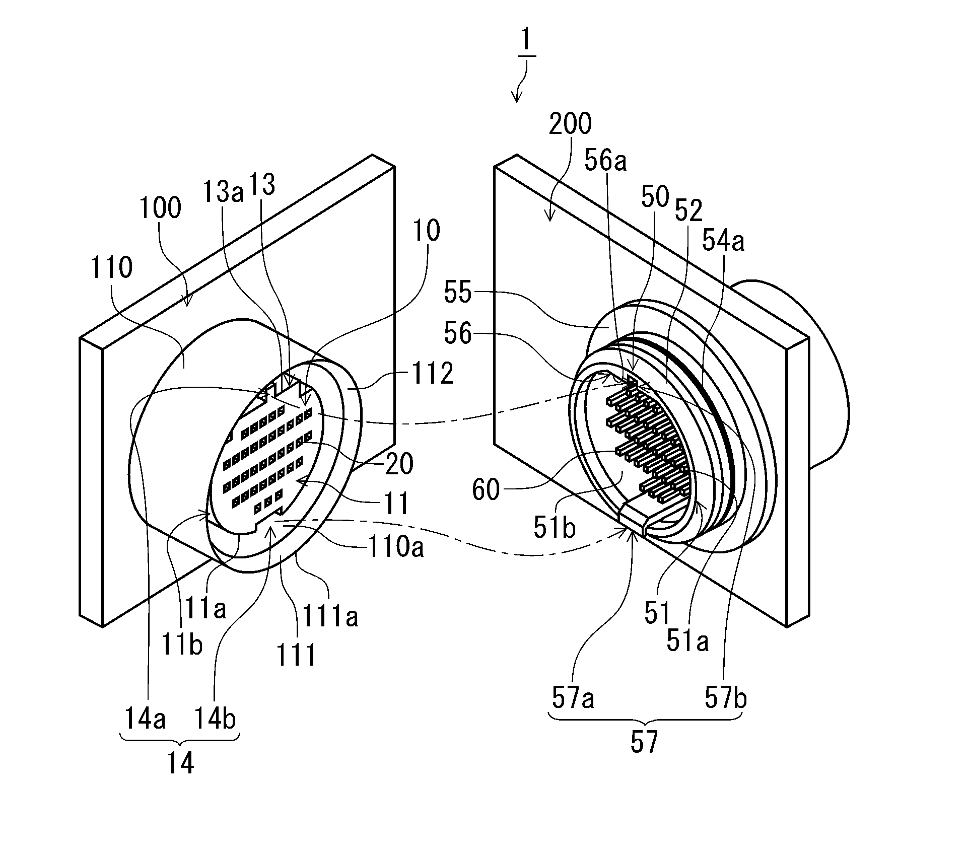
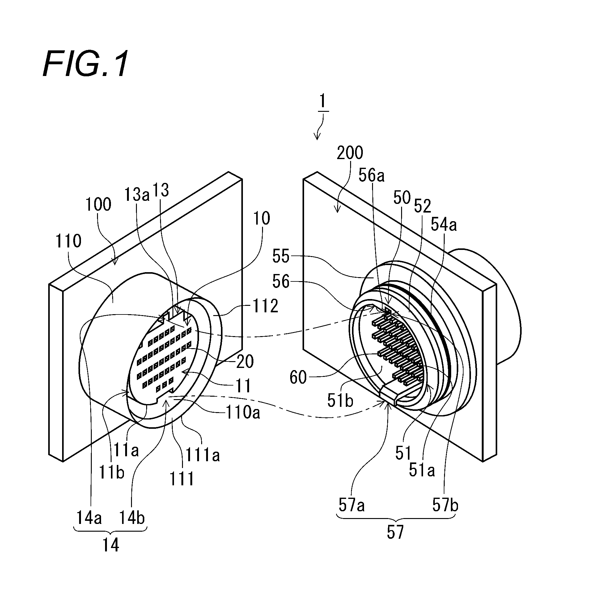
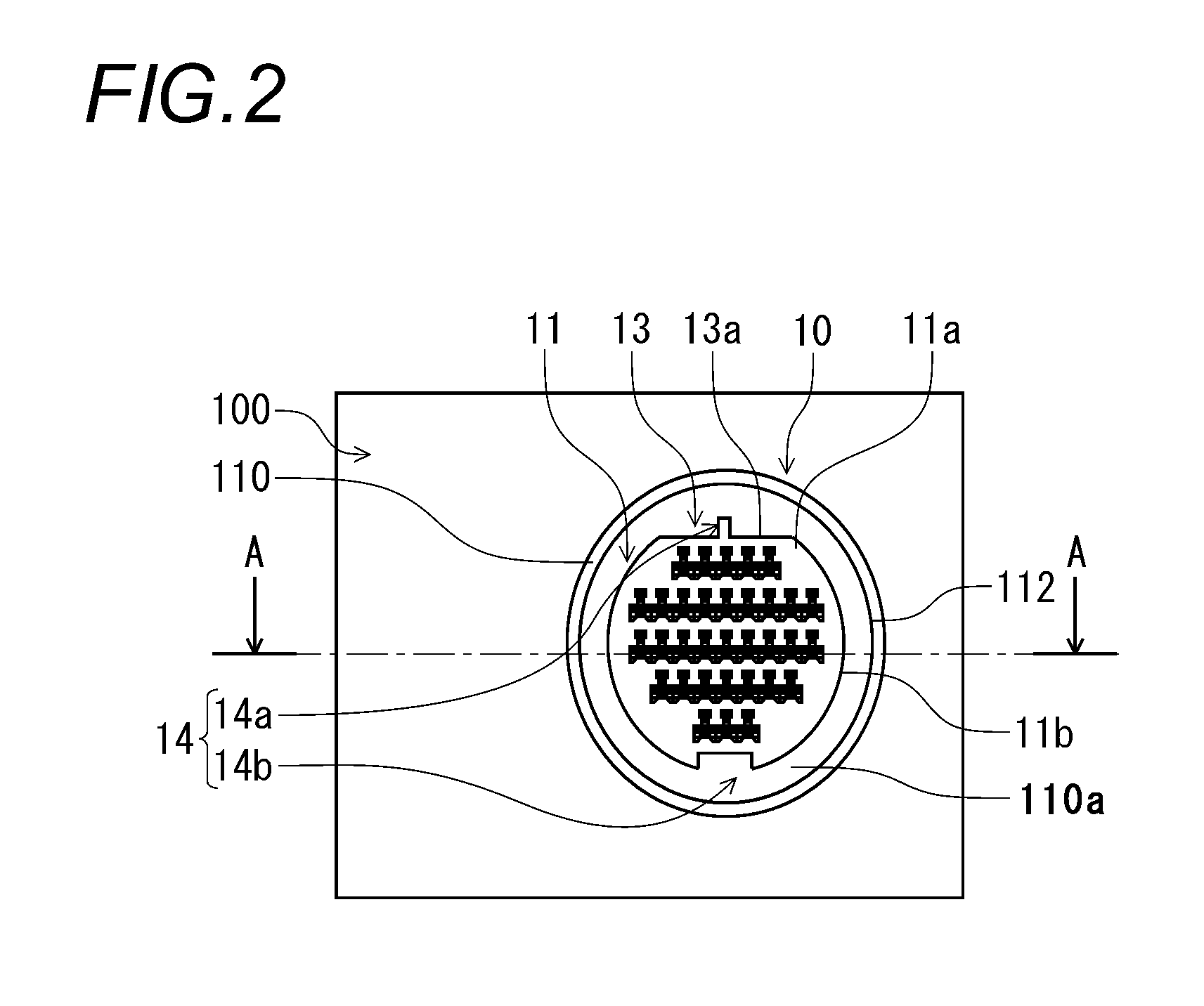
[0035]FIG. 1 is a perspective view depicting a state resulting before a male connector 10 and a female connector 50 of a connector unit 1 according to an embodiment of the disclosure are fitted together. FIG. 2 is a view of the male connector 10 depicted in FIG. 1 as seen from a direction in which the male connector 10 is fitted. FIG. 3 is a sectional view of the male connector 10 taken along the line A-A in FIG. 2. FIG. 4 is a view of the female connector 50 depicted in FIG. 1 as seen from a direction in which the female connector 50 is fitted. FIG. 5 is a sectional view of the female connector 50 taken along the line B-B in FIG. 4. FIG. 6 is a sectional view of a main part of the connector unit 1 depicted in FIG. 1 depicting a state in which the male connector 10 and the female connector 50 are fitted together. FIG. 7 is a sectional vie...


PUM


Abstract

A connector unit has a male connector that includes a cylindrical proximal portion in which a female terminal is accommodated, and a female connector that includes a tubular proximal portion in which a male terminal is held. The cylindrical proximal portion has a cylinder side marking portion including a flat surface formed on a part of an outer circumferential surface thereof, and a cylinder side rotation restricting portion including a groove portion or a projecting portion formed on the outer circumferential surface thereof. The tubular proximal portion has a tube side marking portion including a flat surface formed on an inner surface circumferential surface of the tubular proximal portion, and a tube side rotation restricting portion including a projecting portion projected from the inner circumferential surface or a groove portion formed in the inner circumferential surface.

Description

CROSS REFERENCE TO RELATED APPLICATIONS[0001]This application is a continuation of PCT application No. PCT / JP2013 / 052288, which was filed on Jan. 25, 2013 based on Japanese Patent Application (No. 2012-013034) filed on Jan. 25, 2012, the contents of which are incorporated herein by reference.BACKGROUND OF THE INVENTION[0002]1. Field of the Invention[0003]The present invention relates to a connector unit in which female terminals and male terminals are connected by fitting a male connector and a female connector together.[0004]2. Description of the Related Art[0005]Conventionally, there are connector units that have a male connector holding female terminals and a female connector holding male terminals and in which the female terminals and the male terminals are connected together by fitting the male connector in the female connector. In some of these connector units, the male connector accommodates the female terminals in a cylindrical proximal portion, and the female connector hold...

Claims


Application Information

Patent Timeline
Patent Type & Authority Applications(United States)
IPC IPC(8): H01R13/641H01R13/629
CPCH01R13/641H01R13/629H01R13/6456H01R13/6453
Inventor SATO, AKIRATAKAHASHI, KAZUHIDEOKAMOTO, TOMONARINIMURA, KAZUHISA
Owner YAZAKI CORP
Why Eureka
Try Eureka