Combustors with complex shaped effusion holes

a technology of combustion chamber and effusion hole, which is applied in the direction of efficient propulsion technology, machines/engines, lighting and heating apparatus, etc., can solve the problem of cooling remaining a challeng

Active Publication Date: 2014-11-20
HONEYWELL INT INC
View PDF3 Cites 44 Cited by
  • Summary
  • Abstract
  • Description
  • Claims
  • Application Information

AI Technical Summary

Problems solved by technology

However, given the high temperature of eng

Method used


Image

  • Combustors with complex shaped effusion holes
  • Combustors with complex shaped effusion holes
  • Combustors with complex shaped effusion holes

Examples


Embodiment Construction

[0023]The following detailed description is merely exemplary in nature and is not intended to limit the invention or the application and uses of the invention. Furthermore, there is no intention to be bound by any theory presented in the preceding background or the following detailed description.

[0024]Exemplary embodiments described herein provide a combustor having single-walled or dual-walled liners with effusion and / or impingement cooling holes having complex shapes. For example, the effusion cooling holes may have a non-linear line of sight arrangement. As an additional example, the effusion cooling holes may be at least partially formed by a tube portion extending outward from the cold and / or hot side of the combustion liner. Moreover, effusion cooling holes may have multiple outlets. Such effusion cooling holes may be formed by additive manufacturing techniques.

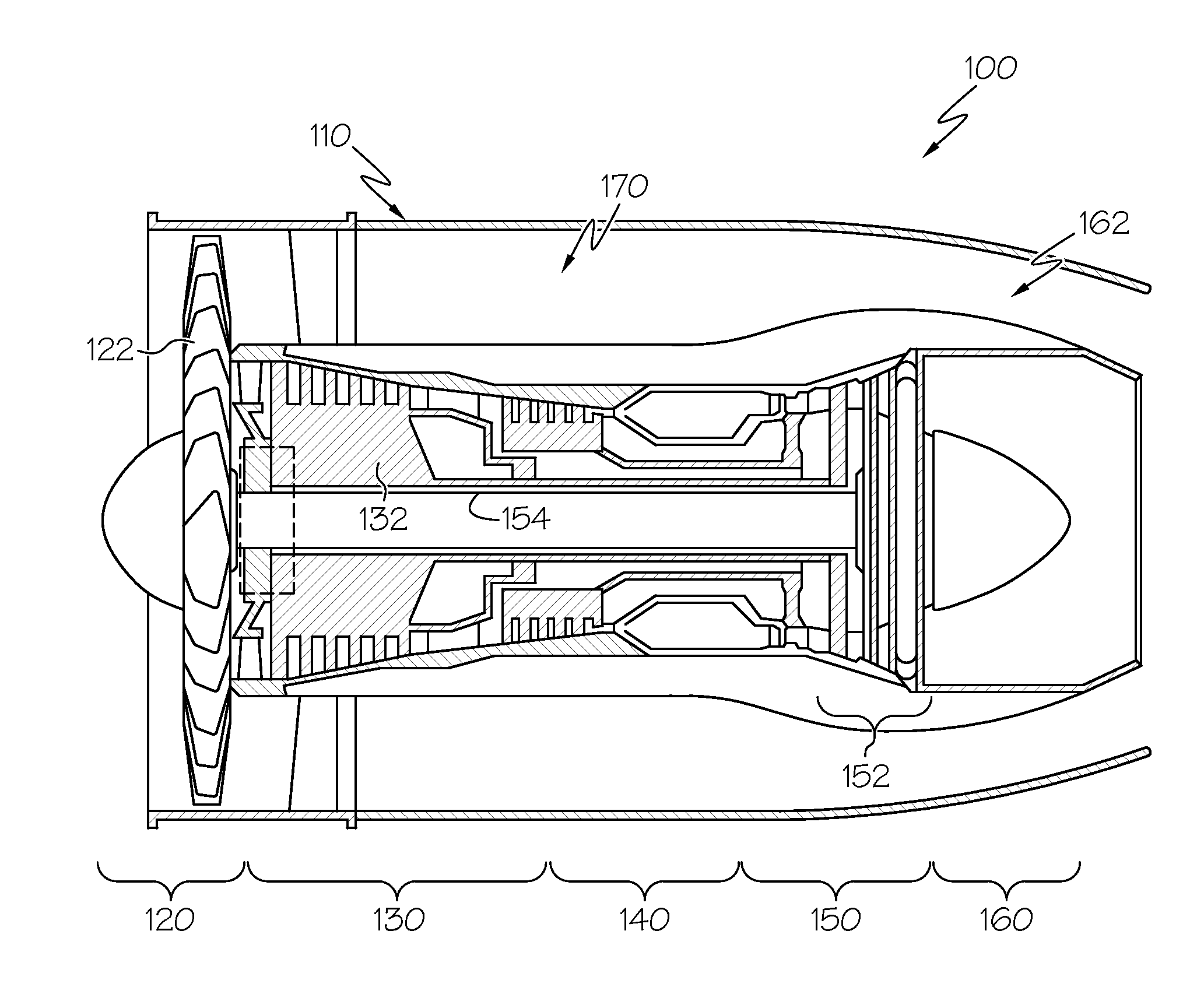
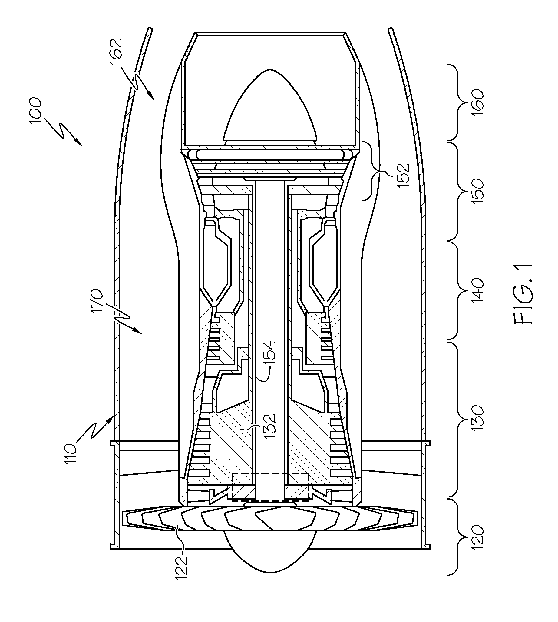
[0025]FIG. 1 is a simplified, cross-sectional view of a gas turbine engine 100 according to an embodiment. The engine...


PUM

PropertyMeasurementUnit
Angleaaaaaaaaaa

Abstract

A combustor is provided for a turbine engine. The combustor includes a first liner having a first side and a second side and a second liner having a first side and a second side. The second side of the second liner forms a combustion chamber with the second side of the first liner, and the combustion chamber is configured to receive an air-fuel mixture for combustion therein. The first liner defines a plurality of effusion cooling holes configured to form a film of cooling air on the second side of the first liner. The plurality of effusion cooling holes including a first effusion cooling hole extending from the first side to the second side with a non-linear line of sight.

Description

TECHNICAL FIELD[0001]The following discussion generally relates to gas turbine engine combustors, and more particularly, to combustors with complex shaped effusion holes.BACKGROUND[0002]Gas turbine engines are generally used in a wide range of applications, such as aircraft engines and auxiliary power units. In a gas turbine engine, air is compressed in a compressor, and mixed with fuel and ignited in a combustor to generate hot combustion gases, which flow downstream into a turbine section for energy extraction. The combustor typically includes radially spaced apart inner and outer liners. The inner and outer liners generally define an annular combustion chamber between the compressor and the turbine.[0003]Due to the high temperatures in many gas turbine engine applications, it is desirable to regulate the operating temperature of certain engine components, particularly those within the mainstream hot gas flow path in order to prevent overheating and potential mechanical issues att...

Claims


Application Information

Patent Timeline
IPC IPC(8): F23R3/00
CPCF23R2900/03041F23R3/002F23R3/06F23R3/16F23R3/50F23R2900/00018F23R2900/03042Y10T29/49231Y02T50/60
Inventor GAGE, RAYMONDRUDRAPATNA, NAGARAJA S.
Owner HONEYWELL INT INC
Why Eureka
Try Eureka