Laser marker

Inactive Publication Date: 2014-11-20
TANG ZHEN
View PDF0 Cites 6 Cited by
  • Summary
  • Abstract
  • Description
  • Claims
  • Application Information

AI Technical Summary

Benefits of technology

[0005]The primary object of this invention is to provide a laser pointer/marker that can generate a circular or elliptical pattern. The size of the pattern is proportional to the distance between laser pointer and illuminated target

Problems solved by technology

The typically small sized spot can be difficult to distinguish when projected upon a large screen.
Another disadvantage for a laser pointer often is the brightness of the spot, so that can make viewers very uncomfortable

Method used


Image

  • Laser marker
  • Laser marker
  • Laser marker

Examples


Example

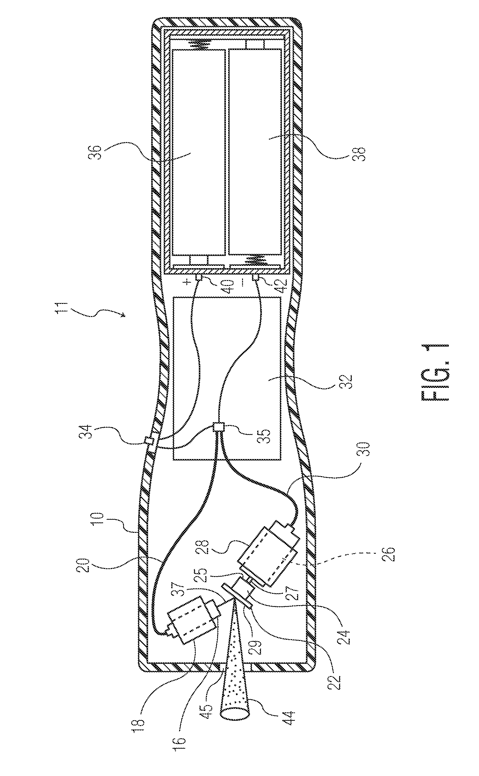
[0014]As shown in FIG. 1, the preferred embodiment of a device 11 according to the present invention for generating circular and elliptical laser patterns comprises a handheld housing or shell body 10, laser diode unit 16, mirror 22, electric motor 26, electric circuit board 32 to drive the motor 26, batteries 36 and 38, and a switch 34 operable for actuating device 11 by applying power from batteries 36, 38 to motor drive circuit 32 and laser diode unit 16.

[0015]The external shell body 10 houses the components of the device 11. The shell body 10 is typically cuboid shaped with rounded edges but can also use other more esthetically appealing curvy shapes. A laser diode beam generating unit 16 is powered by two batteries 36 and 38 controlled by an electric switch 34. The switch on the shell body 10 is positioned at a 10 location for users to conveniently access. The diode laser unit 16 is attached to the shell body 10 by a mounting part 18, and motor 26 by a mounting part 28. A cut-a...


PUM


Abstract

A laser marker/pointer for projecting circular or elliptical laser beam patterns onto a target surface such as a portion of a presentation screen or to assist in the aiming of a firearm, comprises a handheld shell body in which is mounted a laser light source, a rotating optical mirror driven by a motor, and an electronic drive circuit, whereby the aspect ratio of the marking pattern is determined by the geometric relationship of the motor shaft axis, the laser beam, and the mirror surface. The motor drive circuit when initially powered (along with the laser diode), applies full power (a continuous DC voltage to the motor to overcome inertia), followed by a pulsed voltage to lower the duty cycle of the motor, increase battery life, and reduce rotational noise.

Description

FIELD OF THE INVENTION[0001]The present invention is related generally to laser pointers, and more specifically to laser markers operable for projecting circular or elliptical illuminated patterns.BACKGROUND OF THE INVENTION[0002]In conference and meeting presentations, a presenter often uses a laser pointer to highlight portions of a projected viewgraph or slide presentation so that an associated oral message can be better understood by the audience. The conventional laser pointer projects only a small bright spot. The typically small sized spot can be difficult to distinguish when projected upon a large screen. Another disadvantage for a laser pointer often is the brightness of the spot, so that can make viewers very uncomfortable if their eyes focus on the spot.[0003]An illuminated spot may also be used to assist in the aiming of a firearm to improve targeting accuracy during hunting. The small size of the mark can also be a disadvantage as it is difficult to be noticed far away....

Claims


Application Information

Patent Timeline
IPC IPC(8): G02B26/08G02B27/20
CPCG02B27/20G02B26/0816G02B26/105H01S5/0071H01S5/02H01S5/042
Inventor TANG, ZHEN
Owner TANG ZHEN
Why Eureka
Try Eureka