System for monitoring pipeline leakage, pipeline element provided with the system, and method for mounting the monitoring system onto a pipeline

Active Publication Date: 2018-01-25
WIDECO SWEDEN
View PDF4 Cites 3 Cited by
  • Summary
  • Abstract
  • Description
  • Claims
  • Application Information

AI Technical Summary

Benefits of technology

[0016]A major advantage of the present invention is that leakage from non-insulated pipes can be quickly identified. Moreove

Problems solved by technology

The most common problems with these non-insulated pipelines located underground or above ground are leaky joints.
The reason for leakage at pipe joints may be that the rubber ring at one end of the pipe has not been mounted, leaks in the rubber ring joint due to dirt between rubber ring and pipe, damaged rubber ring, the tip end not being sufficiently inserted into the sleeve, excess deflection in the sleeve etc. causing the leakages.
Damaged mirror welds between pipes can be found.
This may occur due to improper welding temperature, inadequately cleaned weld surfaces, weld surfaces not being flat, etc.
This can have major negative consequences for the affected operations, breakdowns, costs of leaking drinking water and ga

Method used


Image

  • System for monitoring pipeline leakage, pipeline element provided with the system, and method for mounting the monitoring system onto a pipeline
  • System for monitoring pipeline leakage, pipeline element provided with the system, and method for mounting the monitoring system onto a pipeline
  • System for monitoring pipeline leakage, pipeline element provided with the system, and method for mounting the monitoring system onto a pipeline

Examples


Embodiment Construction

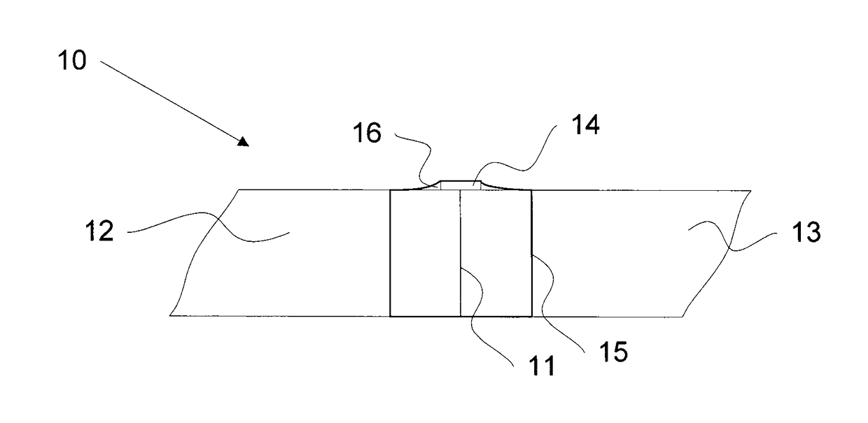
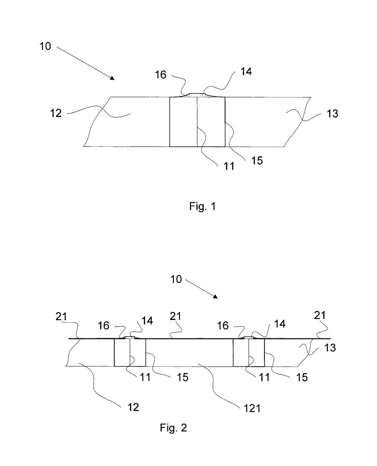
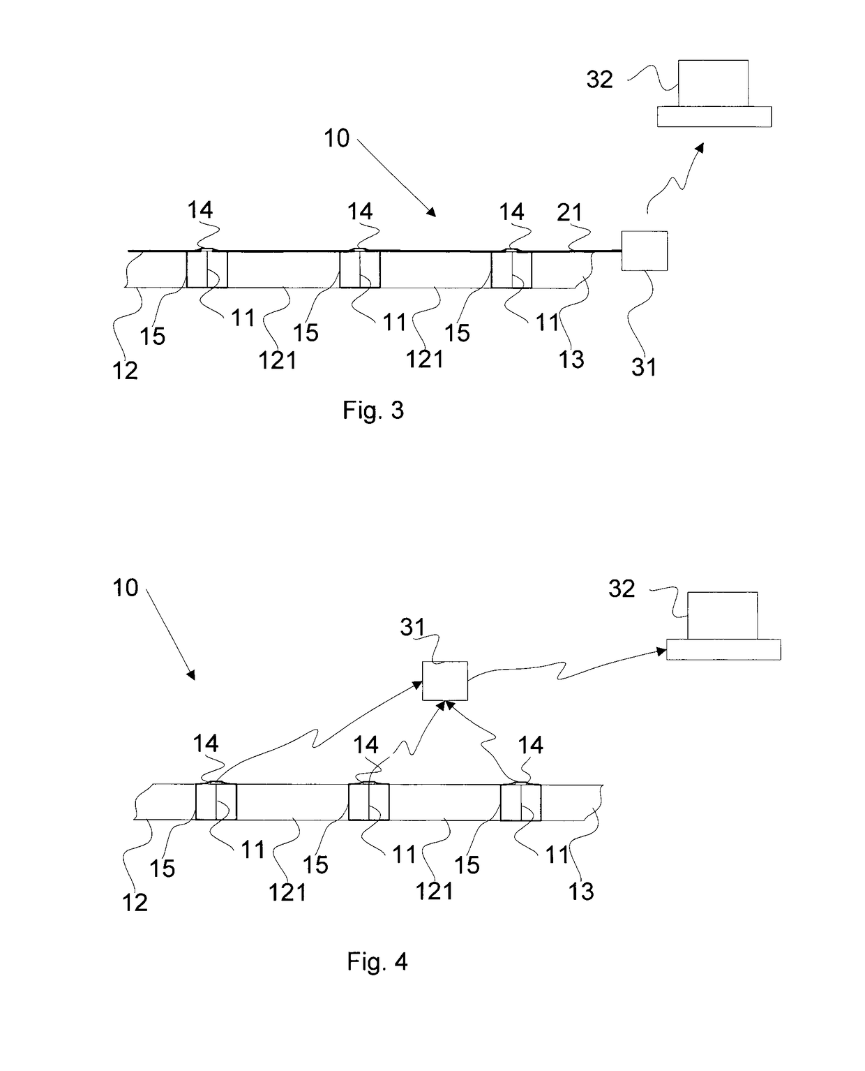
[0027]FIG. 1 describes a monitoring system 10 for the identification and location of leakage of a fluid at a pipe joint 11 consisting of two abutting non-insulated pipes or piping elements 12, 13 for fluids. A piping element can, for example, be a pipe bend, a ‘T’ piece, or a valve. A detector 14 for detecting fluid is located at the pipe joint 11. A jacket piece 15 is provided locally over the pipe joint 11. The jacket piece 15, together with the non-insulated pipes 12, 13, 121, forms a sealed space 16 containing the first detector. An advantage of the monitoring system according to FIG. 1 is that it is significantly less expensive than the solutions using fully jacketed pipes, as only one local jacket piece over the pipe joint is needed.

[0028]The jacket piece can consist of a so-called crimp sleeve which is crimped around the pipe joint after the detector has been positioned there. The mantle piece may be formed with an inner layer of bitumen or mastic providing a water- and gasti...


PUM


Abstract

A monitoring system is provided for the identification and location of leakage of a fluid at least one pipe joint consisting of two abutting non-insulated pipes. The monitoring system comprises at least one first detector for detecting fluid, located at a first pipe joint, and a jacket piece provided locally over the first pipe joint, the jacket piece together with the non-insulated pipes forming a sealed space containing the first detector.

Description

FIELD OF THE INVENTION[0001]The invention relates generally to systems for monitoring piping leakage from non-insulated pipes, fittings and joints of pipes for fluids, including pipes of steel, nodular cast iron, concrete or plastic. The invention relates particularly to a system for monitoring piping leakage and to a pipeline element provided with the system and a method for mounting the same.BACKGROUND[0002]Non-insulated pipelines are made up of joined piping elements such as pipes and fittings. Such pipelines can be, for example, pipes for drinking water, wastewater, storm water, oil pipelines, gas pipelines, district cooling pipes, or district heating pipes. Several of these pipelines are normally located underground or underwater (under ditch pipelines). Pipelines for industries, refineries, etc. are also joined using non-insulated pipes and fittings and are usually located above ground. Pipes and fittings are typically made of metal or plastic, and pipes of abutting piping ele...

Claims


Application Information

Patent Timeline
IPC IPC(8): G01M3/18G08B21/18
CPCG01M3/183G08B21/18
Inventor WIRFALK, ARNOLD
Owner WIDECO SWEDEN
Why Eureka
Try Eureka