Communication device

a communication device and a technology of a diaphragm are applied in the field of communication devices, which can solve the problems of difficult to hear the sound, easy to be lost among the air conduction sound, and the strong vibration produced in the bone conduction of the skull is not suitable for devices such as mobile phones, so as to achieve the effect of reducing power consumption, facilitating hearing, and reducing nois

Active Publication Date: 2014-11-20
KDDI CORP
View PDF7 Cites 49 Cited by
  • Summary
  • Abstract
  • Description
  • Claims
  • Application Information

AI Technical Summary

Benefits of technology

[0035]According to the present invention, the communication device is able to conduct vibration, in addition to air conduction sound, to the human body even in an environment in which sound is hard to be heard only with air conduction sound, for example, and transmitted sound may be easily heard.
[0036]Further, the communication device according to

Problems solved by technology

However, there may be a problem that it is difficult to hear the sound only with air conduction sound, when noises are larger than the air conduction sound.
However, strong vibration as produced in bone conduction that vibrates bones of the skull is not suitable for devices such as mobile phones that use little electricity in terms of power consumption.
As the sound by bone conduction is small in the first place, it may be easily lost among the air conduction sound.
Therefore, there is a drawback that a manufacturing process becomes complicated as it is neces

Method used


Image

  • Communication device
  • Communication device
  • Communication device

Examples


first embodiment

[0055](First Embodiment)

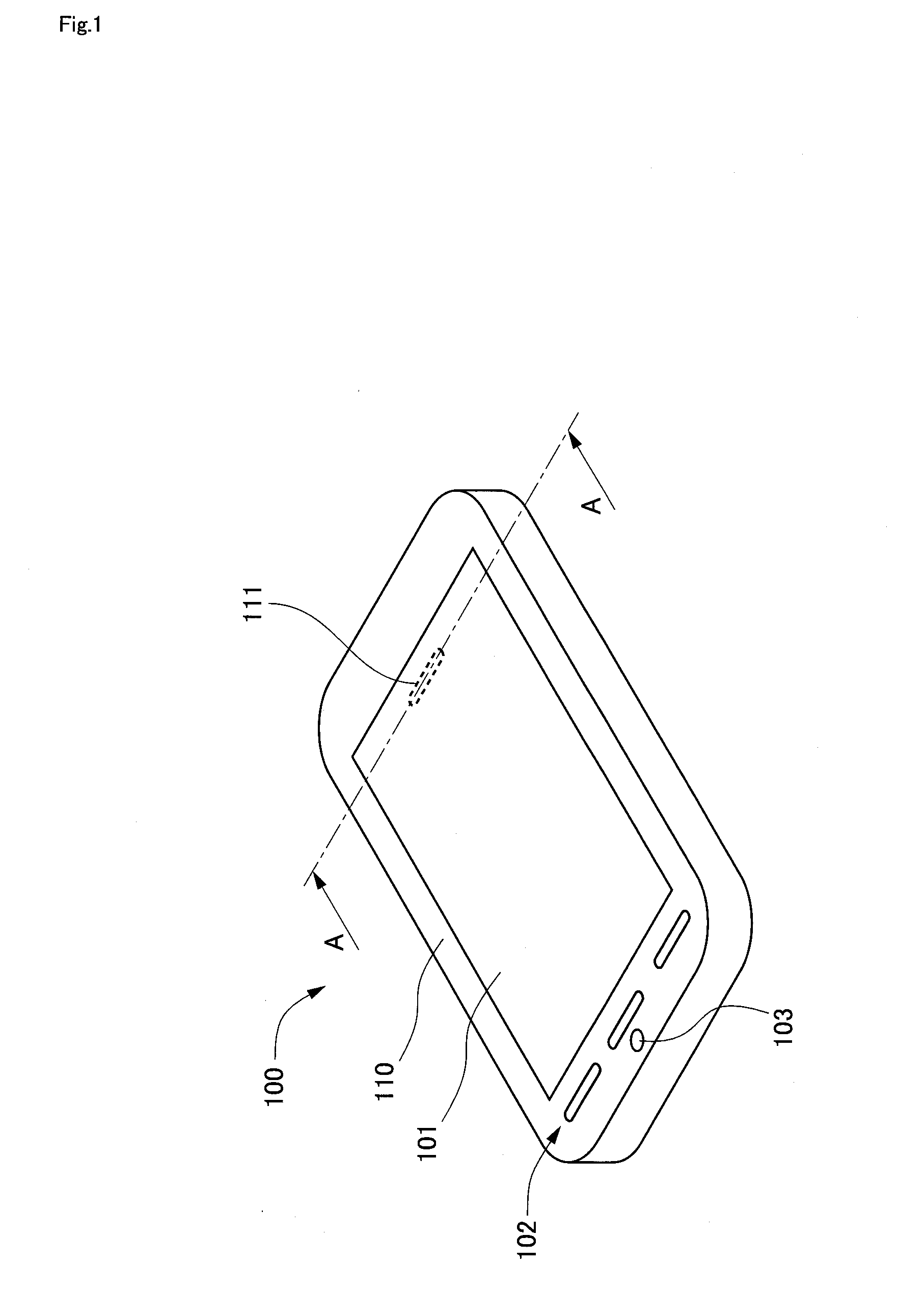
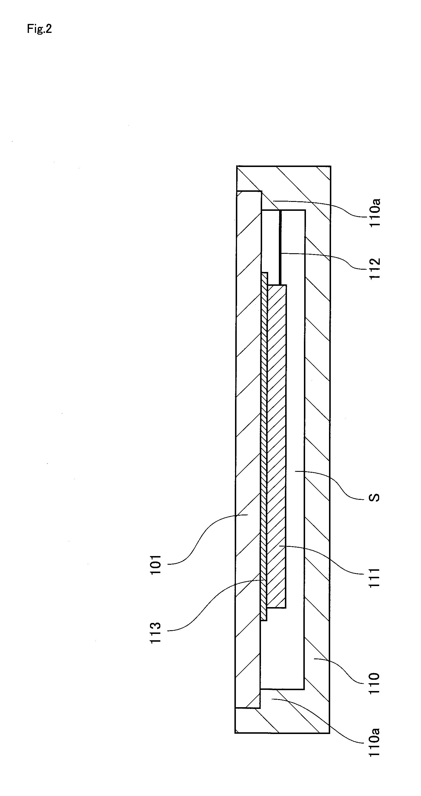
[0056]FIG. 1 is a perspective view illustrating a communication device 100 according to a first embodiment.

[0057]The drawings, including FIG. 1, are schematic, and sizes and shapes of components are shown figuratively as needed in order to facilitate understanding.

[0058]In the following description, a surface shown in FIG. 1 is called a front surface, and a surface not shown is called a back surface.

[0059]The communication device 100 is a mobile phone terminal including a protecting panel 101, an operation key 102, and a microphone 103 on the front surface of a casing 110.

[0060]The protecting panel 101 is provided over a display screen, and configured as a contact member allowing sound transmission using cartilage conduction according to the present invention by having at least a portion of the protecting panel 101 be brought into contact with a user's ear or a human body around the ear. The protecting panel 101 is preferably made of a transparent resin mater...

second embodiment

[0084](Second Embodiment)

[0085]FIG. 3 is a perspective view illustrating a communication device 200 according to a second embodiment.

[0086]In the following description, a surface shown in FIG. 3 is called a front surface, and a surface not shown is called a back surface.

[0087]Components that serve the same functions as those in the first embodiment described above are denoted by the same suffix reference numerals, and descriptions that may be overlapping shall be omitted.

[0088]Similarly to the communication device 100 according to the first embodiment, the communication device 200 according to the second embodiment is a mobile phone terminal including a protecting panel 201, an operation key 202, and a microphone 203 on the front surface of a casing 210.

[0089]However, the communication device 200 according to the second embodiment is provided with an transducer 211 at a portion different from the case in the first embodiment. Specifically, the transducer 211 is surface joined from t...

third embodiment

[0101](Third Embodiment)

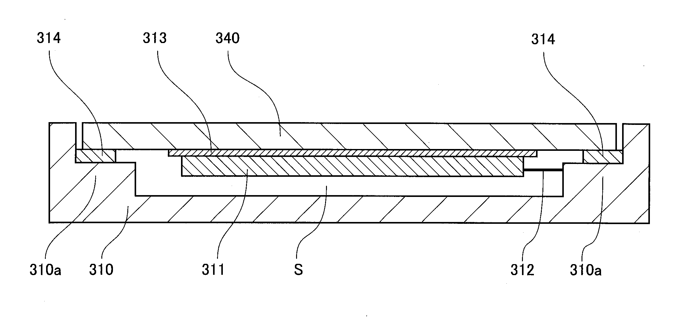
[0102]FIG. 5 is a perspective view illustrating a communication device 300 according to a third embodiment.

[0103]Components that serve the same functions as those in the first embodiment described above are denoted by the same suffix reference numerals, and descriptions that may be overlapping shall be omitted.

[0104]The communication device 300 according to the third embodiment is a foldable mobile phone terminal in which a first casing 310 and a second casing 320 are configured as movable parts rotatably movable via a shaft section 330.

[0105]While the protecting panel 101 or the casing 210 also serves as the contact member in the communication device according to the first embodiment and the second embodiment, the communication device 300 according to the third embodiment is provided with a contact member separately from a casing or the like.

[0106]FIG. 5 shows a use state in which the first casing 310 and the second casing 320 are unfolded. In the following ...


PUM


Abstract

Provided is a communication device that facilitates hearing even in an environment in which hearing of sound is difficult only with air conduction sound, and requires fewer components, facilitates implementation. The communication device 100 includes: a protecting panel 101 serving as a contact member disposed at a position at which at least a part of the contact member is brought into contact with a user's ear and/or a human body around the ear; and an transducer 111 surface joined to the protecting panel 101, and configured to vibrate in a frequency band of an audible range such that vibration is not conducted from the protecting panel 101 to an auditory organ of the user via bones of a skull of the user.

Description

TECHNICAL FIELD[0001]The present invention relates to a communication device such as a mobile phone terminal and a land-line phone terminal.BACKGROUND ART[0002]An application of panel loudspeakers in place of conventional loudspeakers has been known as means for outputting air conduction sound vibrating air when a mobile phone terminal receives a call or reproduces music (see PTL 1, for example). However, there may be a problem that it is difficult to hear the sound only with air conduction sound, when noises are larger than the air conduction sound.[0003]By contrast, it is known that bone conduction is effective where ambient noises are large (see PTL 2, for example). However, strong vibration as produced in bone conduction that vibrates bones of the skull is not suitable for devices such as mobile phones that use little electricity in terms of power consumption. As the sound by bone conduction is small in the first place, it may be easily lost among the air conduction sound. There...

Claims


Application Information

Patent Timeline
IPC IPC(8): H04M1/03H04R7/04
CPCH04M1/03H04R2499/11H04R7/045H04M1/0266
Inventor SUZUKI, MASAHIROWAKAMATSU, DAISAKU
Owner KDDI CORP
Why Eureka
Try Eureka