Electronic device

a technology of electronic devices and antennas, applied in the field of electronic devices, can solve problems affecting the electromagnetic induction of antennas, and achieve the effect of good magnetic field induction

Active Publication Date: 2014-11-27
ASUSTEK COMPUTER INC
View PDF5 Cites 9 Cited by
  • Summary
  • Abstract
  • Description
  • Claims
  • Application Information

AI Technical Summary

Benefits of technology

[0006]An electronic device is provided. The electronic device includes a complete metal cover and an antenna with a good magnetic field induction effect.
[0008]The electronic device in the disclosure induces an enough external magnetic flux into the antenna in the electronic device via the magnetic flux inducer unit with high permeability through disposing the magnetic flux inducer unit between the original nonmetal covered portion of the metal cover (such as the opening of a camera lens or the opening of a logo) and the antenna, or disposing the magnetic flux inducer unit between the nonmetal frame close to the metal cover and the antenna, so as to prevent the metal cover having a shielding effect to the antenna. The electronic device in the disclosure keeps a complete metal cover and a good product appearance.

Problems solved by technology

However, the external magnetic flux is shielded by the metal cover, which affects the electromagnetic induction of the antenna in the electronic device.

Method used


Image

  • Electronic device
  • Electronic device
  • Electronic device

Examples


first embodiment

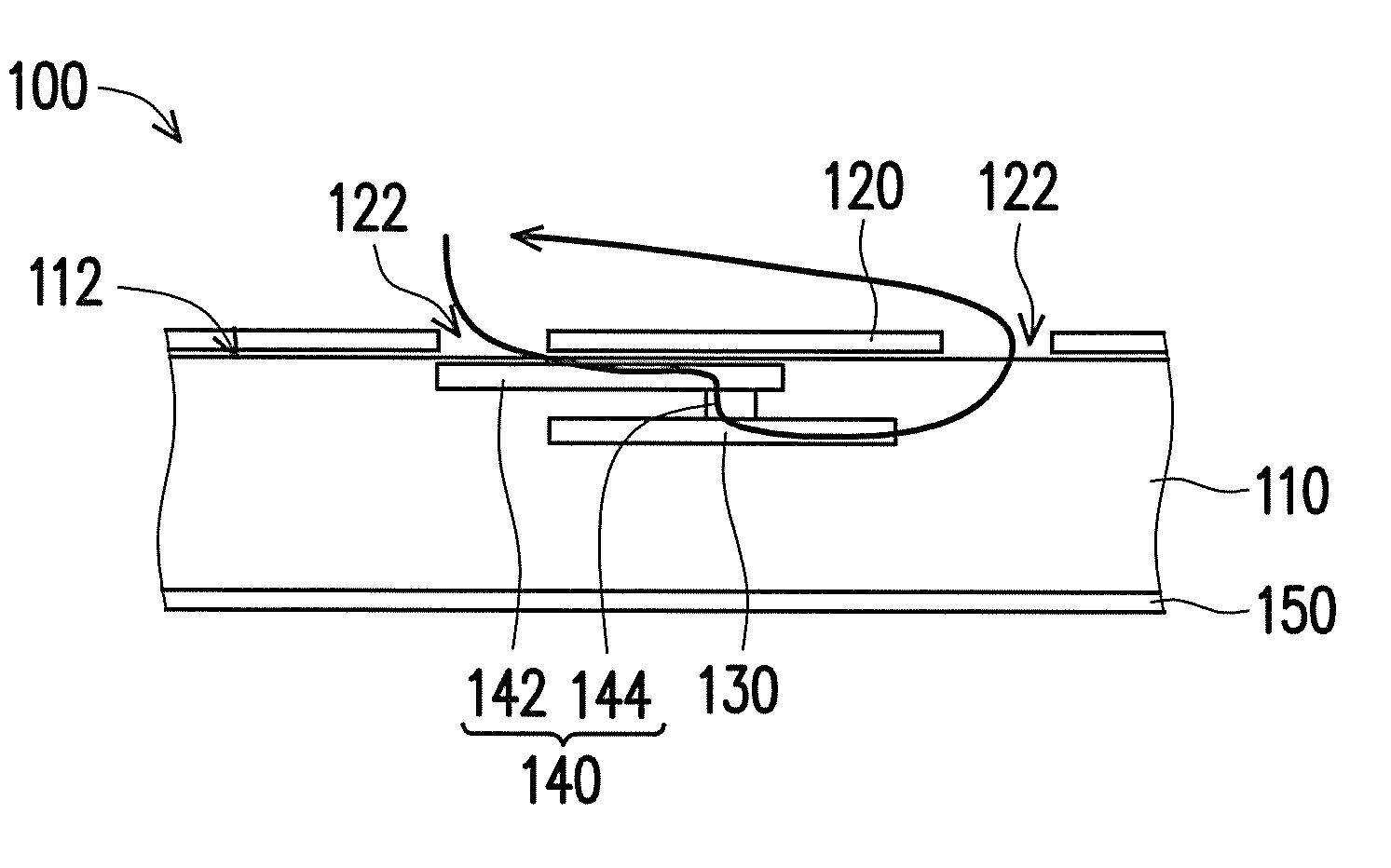
[0016]FIG. 1 is a side view showing partial of an electronic device in the Please refer to FIG. 1, in the embodiment, an electronic device 100 is a mobile phone only including a single main body. In other embodiment, the electronic device 100 may be a tablet computer, a flip mobile phone including two main bodies, which is not limited herein. In FIG. 1, the components, such as a circuit board, controllers, and parts of the casings, which are hidden in the electronic device 100 are not shown for a clear figure.

[0017]In the embodiment, the electronic device 100 includes a main body 110, a metal cover 120, an antenna 130 and a magnetic flux inducer unit 140. The main body 110 includes a first side 112 opposite to a display panel 150, and the metal cover 120 is entirely disposed at the first side 112 of the main body 110 and includes a nonmetal covered portion 122. The position of the nonmetal covered portion 122 is corresponding to the position of a camera lens (not shown), or the pos...

second embodiment

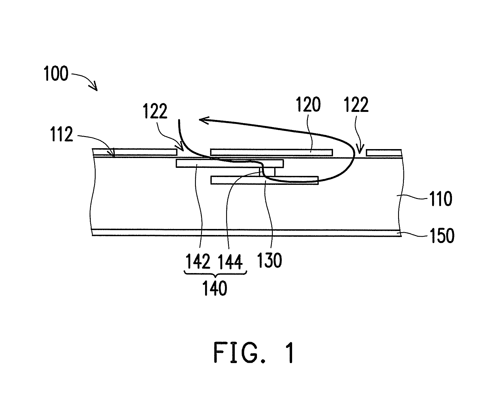
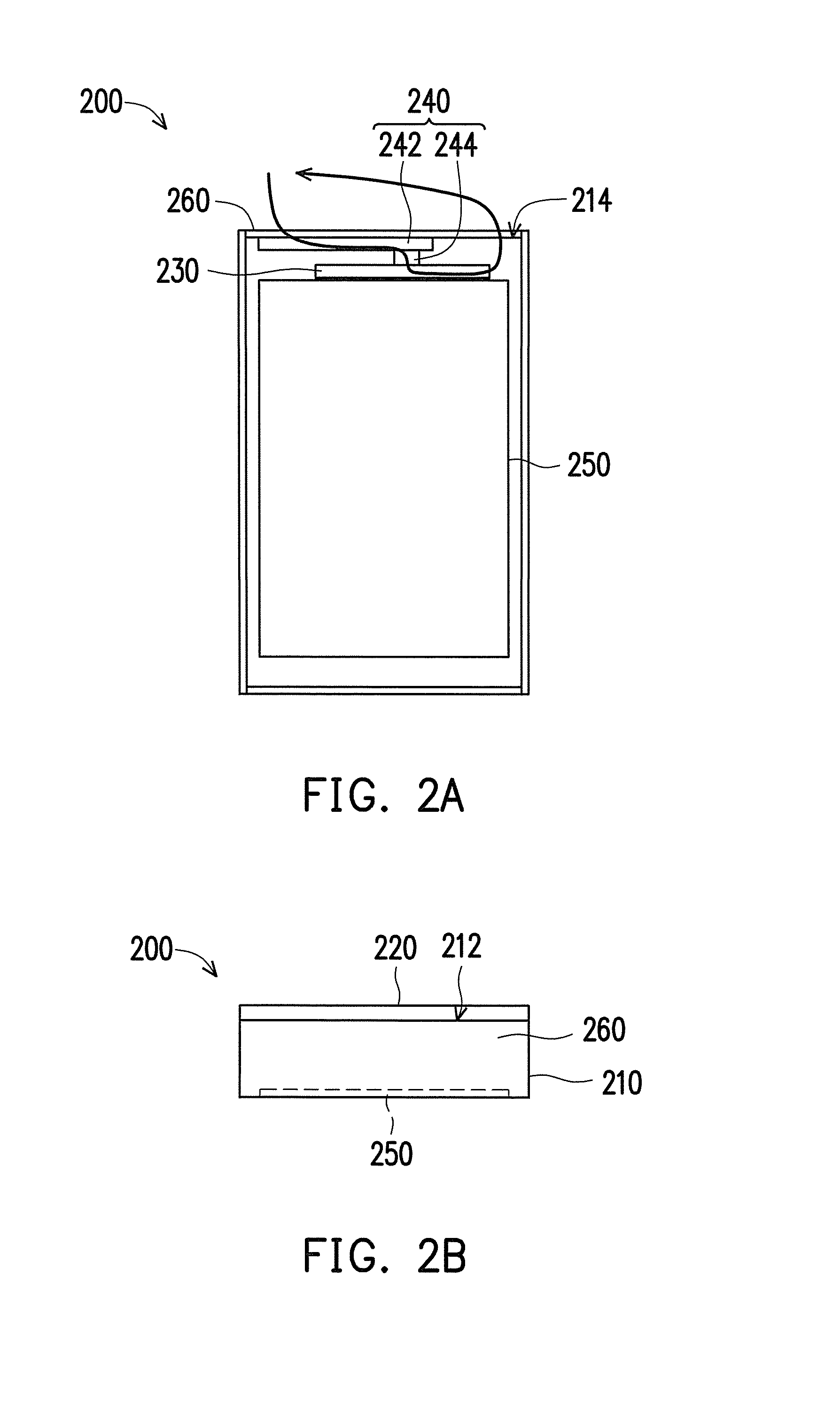
[0023]FIG. 2A is a back view showing an electronic device in a second embodiment, FIG. 2B is a top view showing the electronic device in FIG. 2A. Please refer to FIG. 2A and FIG. 2B. The main difference between the electronic device 200 in FIG. 2A and the electronic device 100 in FIG. 1 is that the magnetic flux in FIG. 1 be induced into and leave out of the electronic device 100 via the nonmetal covered portion 122 of the metal cover 120, and the magnetic flux inducer unit 140 is disposed between the nonmetal covered portion 122 and the antenna 130, in FIG. 2A, in the embodiment, the electronic device 200 further includes a nomnetal material frame 260. The magnetic flux be induced into and leave out of the electronic device 200 via the nonmetal material frame 260, and the magnetic flux inducer unit 240 is disposed between the nonmetal material frame 260 and the antenna 230.

[0024]In detail, in the embodiment, the main body 210 includes a first side 212 and a second side 214 adjacent...

third embodiment

[0026]In the embodiments, the pillar 144 of the magnetic flux inducer unit 140 and the pillar 244 of the magnetic flux inducer unit 240 contact with the central positions of the antenna 130, 230, respectively. In other embodiment, the magnetic flux inducer unit 140, 240 and the antenna 130, 230 are separated by a small gap, respectively, as long as the magnetic flux inducer unit 140, 240 can induce the external magnetic flux to the antenna 130, 230. The relative positions of the magnetic flux inducer unit 140, 240 and the antenna 130, 230 are not limited herein. FIG. 3A is a schematic diagram showing a magnetic flux inducer unit and an antenna of an electronic device in the Please refer to FIG. 3A, in the embodiment, the pillar 344 of the magnetic flux inducer unit 340 extends from the position close to the edge of the board 342 and contacts with the position of the antenna 330 far away from the central of the antenna 330.


PUM


Abstract

An electronic device includes a main body, a metal cover, an antenna and a magnetic flux inducer unit. The metal cover is disposed at the main body and the main body includes a nonmetal covered portion. The antenna is disposed in the main body. The magnetic flux inducer unit is disposed in the main body and located between the nomnetal covered portion and the antenna. The permeability of the magnetic flux inducer unit is greater than 1.

Description

CROSS-REFERENCE TO RELATED APPLICATION[0001]This application claims the priority benefits of U.S. provisional application Ser. No. 61 / 826,988, filed on May 23, 2013 and China application serial no. 201410048864.0, filed on Feb. 12, 2014. The entirety of each of the above-mentioned patent applications is hereby incorporated by reference herein and made a part of this specification.BACKGROUND OF THE INVENTION[0002]1. Field of the Invention[0003]The invention relates to an electronic device and, more particularly, to an electronic device having an antenna.[0004]2. Description of the Related Art[0005]As technology develops, electronic communication devices (such as mobile telephones, tablet computers) are widely used. Recent years, except for the functionality, the requirement of the product appearance is higher. Thus, a metal cover is usually used in the electronic device. However, the external magnetic flux is shielded by the metal cover, which affects the electromagnetic induction of...

Claims


Application Information

Patent Timeline
Patent Type & Authority Applications(United States)
IPC IPC(8): H01Q1/24
CPCH01Q1/241H01Q1/245H01Q1/24H01Q1/242H01Q1/44
Inventor TSENG, BIN-CHYIYEN, TSUNG-CHIEHLIN, CHIH-CHUNG
Owner ASUSTEK COMPUTER INC
Why Eureka
Try Eureka