Electronic device
a technology of electronic devices and antennas, applied in the field of electronic devices, can solve problems affecting the electromagnetic induction of antennas, and achieve the effect of good magnetic field induction
- Summary
- Abstract
- Description
- Claims
- Application Information
AI Technical Summary
Benefits of technology
Problems solved by technology
Method used
Image
Examples
first embodiment
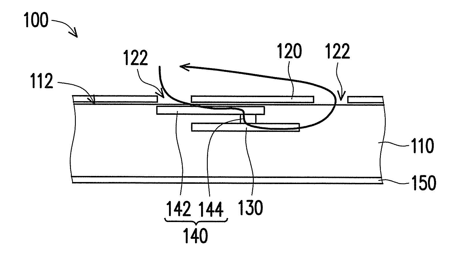
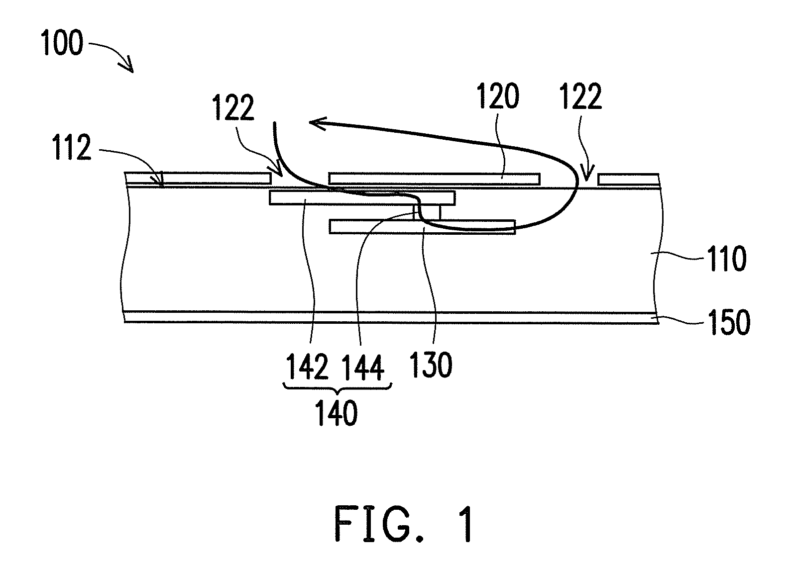
[0016]FIG. 1 is a side view showing partial of an electronic device in the Please refer to FIG. 1, in the embodiment, an electronic device 100 is a mobile phone only including a single main body. In other embodiment, the electronic device 100 may be a tablet computer, a flip mobile phone including two main bodies, which is not limited herein. In FIG. 1, the components, such as a circuit board, controllers, and parts of the casings, which are hidden in the electronic device 100 are not shown for a clear figure.
[0017]In the embodiment, the electronic device 100 includes a main body 110, a metal cover 120, an antenna 130 and a magnetic flux inducer unit 140. The main body 110 includes a first side 112 opposite to a display panel 150, and the metal cover 120 is entirely disposed at the first side 112 of the main body 110 and includes a nonmetal covered portion 122. The position of the nonmetal covered portion 122 is corresponding to the position of a camera lens (not shown), or the pos...
second embodiment
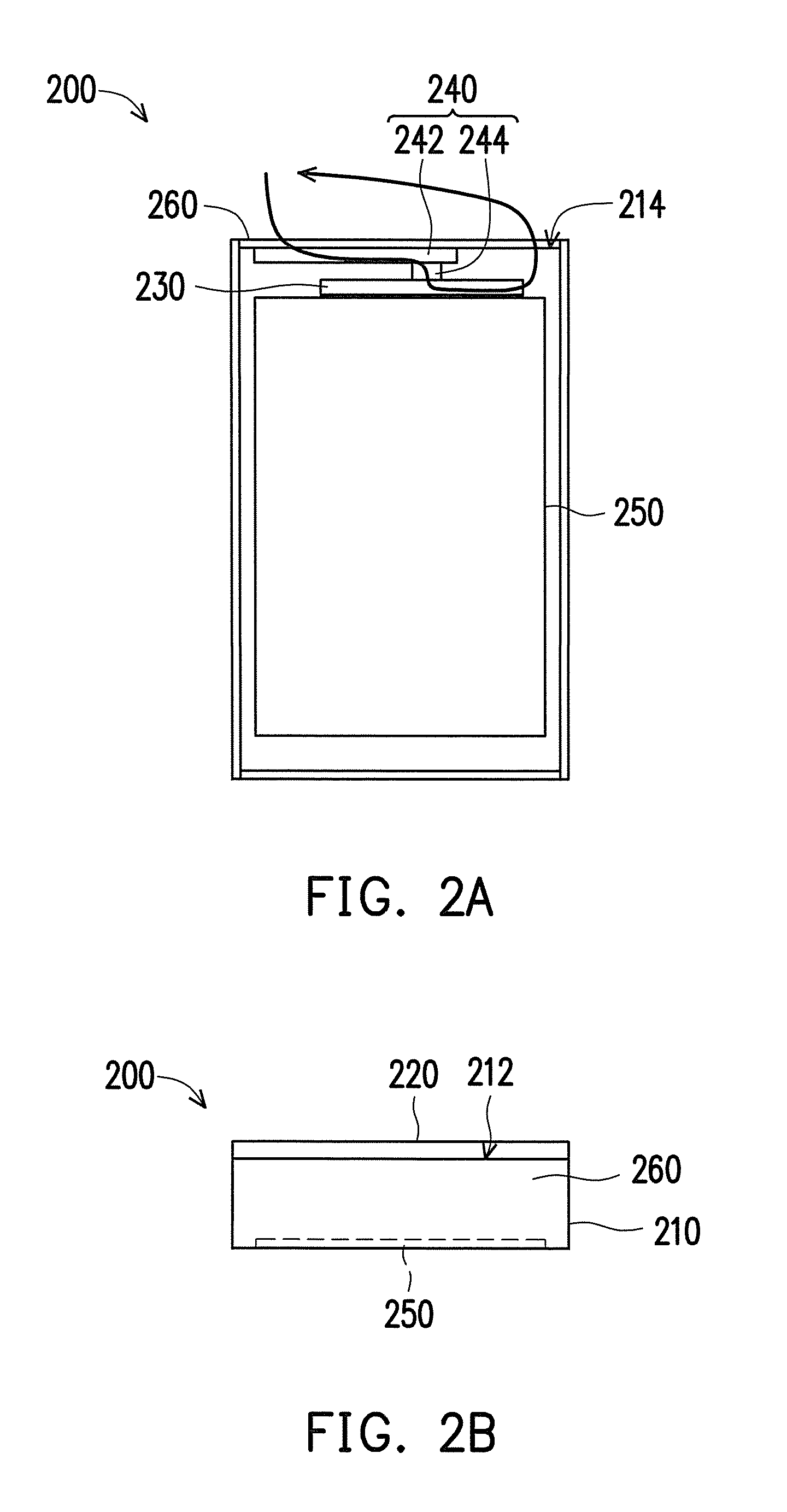
[0023]FIG. 2A is a back view showing an electronic device in a second embodiment, FIG. 2B is a top view showing the electronic device in FIG. 2A. Please refer to FIG. 2A and FIG. 2B. The main difference between the electronic device 200 in FIG. 2A and the electronic device 100 in FIG. 1 is that the magnetic flux in FIG. 1 be induced into and leave out of the electronic device 100 via the nonmetal covered portion 122 of the metal cover 120, and the magnetic flux inducer unit 140 is disposed between the nonmetal covered portion 122 and the antenna 130, in FIG. 2A, in the embodiment, the electronic device 200 further includes a nonmetal material frame 260. The magnetic flux be induced into and leave out of the electronic device 200 via the nonmetal material frame 260, and the magnetic flux inducer unit 240 is disposed between the nonmetal material frame 260 and the antenna 230.
[0024]In detail, in the embodiment, the main body 210 includes a first side 212 and a second side 214 adjacent...
third embodiment
[0026]In the embodiments, the pillar 144 of the magnetic flux inducer unit 140 and the pillar 244 of the magnetic flux inducer unit 240 contact with the central positions of the antenna 130, 230, respectively. In other embodiment, the magnetic flux inducer unit 140, 240 and the antenna 130, 230 are separated by a small gap, respectively, as long as the magnetic flux inducer unit 140, 240 can induce the external magnetic flux to the antenna 130, 230. The relative positions of the magnetic flux inducer unit 140, 240 and the antenna 130, 230 are not limited herein. FIG. 3A is a schematic diagram showing a magnetic flux inducer unit and an antenna of an electronic device in the Please refer to FIG. 3A, in the embodiment, the pillar 344 of the magnetic flux inducer unit 340 extends from the position close to the edge of the board 342 and contacts with the position of the antenna 330 far away from the central of the antenna 330.
PUM
 Abstract
Description
Claims
Application Information
 - R&D
- Intellectual Property
- Life Sciences
- Materials
- Tech Scout
- Unparalleled Data Quality
- Higher Quality Content
- 60% Fewer Hallucinations
Browse by: Latest US Patents, China's latest patents, Technical Efficacy Thesaurus, Application Domain, Technology Topic, Popular Technical Reports.
© 2025 PatSnap. All rights reserved.Legal|Privacy policy|Modern Slavery Act Transparency Statement|Sitemap|About US| Contact US: help@patsnap.com


