
Image processing device and image processing method

a technology of image processing and image, applied in the direction of picture signal generators, solid-state device signal generators, television systems, etc., can solve the problem of difficult estimation of crosstalk amount from surrounding pixels, and achieve the effect of reducing color differences

Active Publication Date: 2014-11-27
OLYMPUS CORP
View PDF18 Cites 80 Cited by
  • Summary
  • Abstract
  • Description
  • Claims
  • Application Information

AI Technical Summary

Benefits of technology

The invention aims to create an image processing device and method that can minimize color differences between areas where normal pixels are located and those where phase difference pixels are placed.

Problems solved by technology

With this additive combination, the effects of crosstalk are propagated to pixels around the pixel that is affected by crosstalk, and it is difficult to estimate crosstalk amount from the surrounding pixels.

Method used


Image

  • Image processing device and image processing method
  • Image processing device and image processing method
  • Image processing device and image processing method

Examples


Embodiment Construction

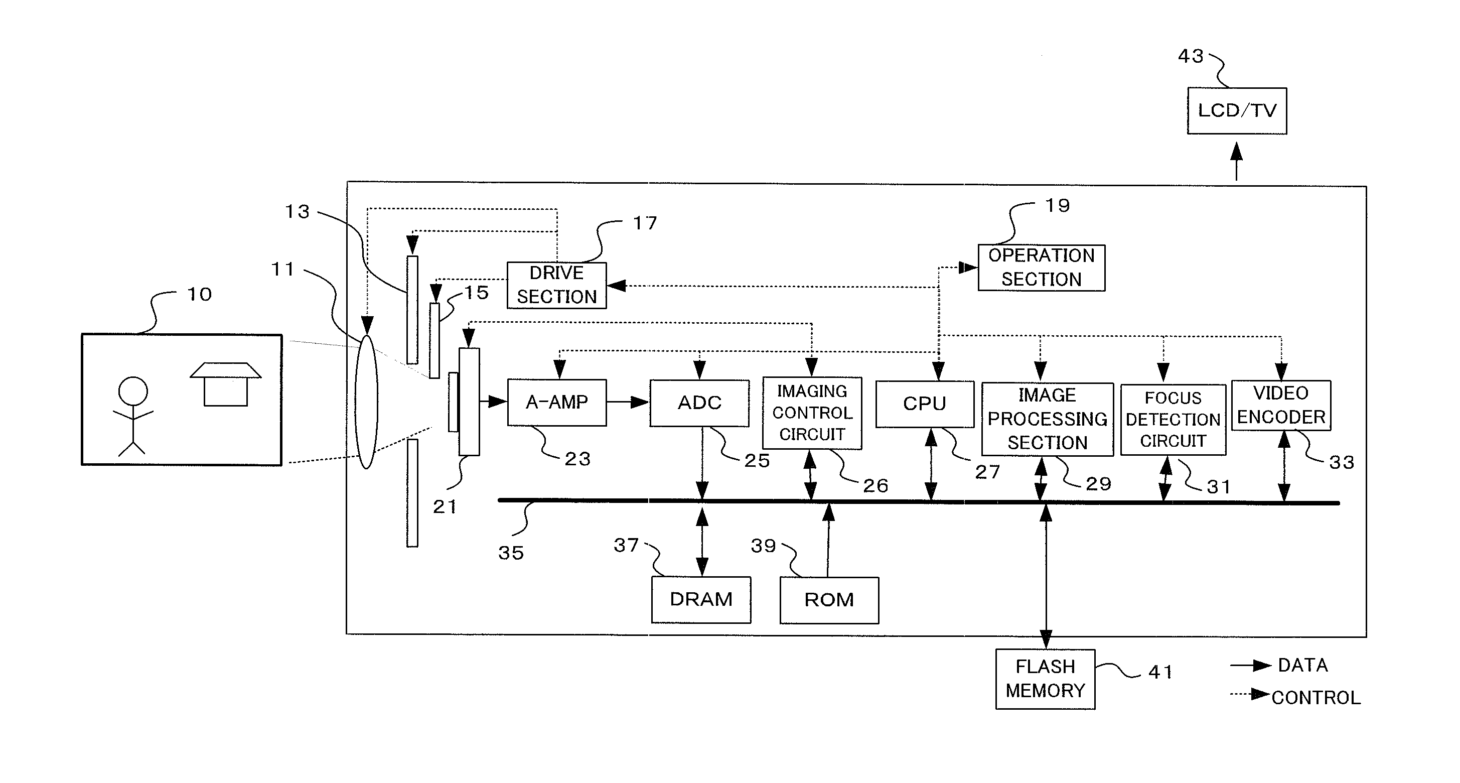
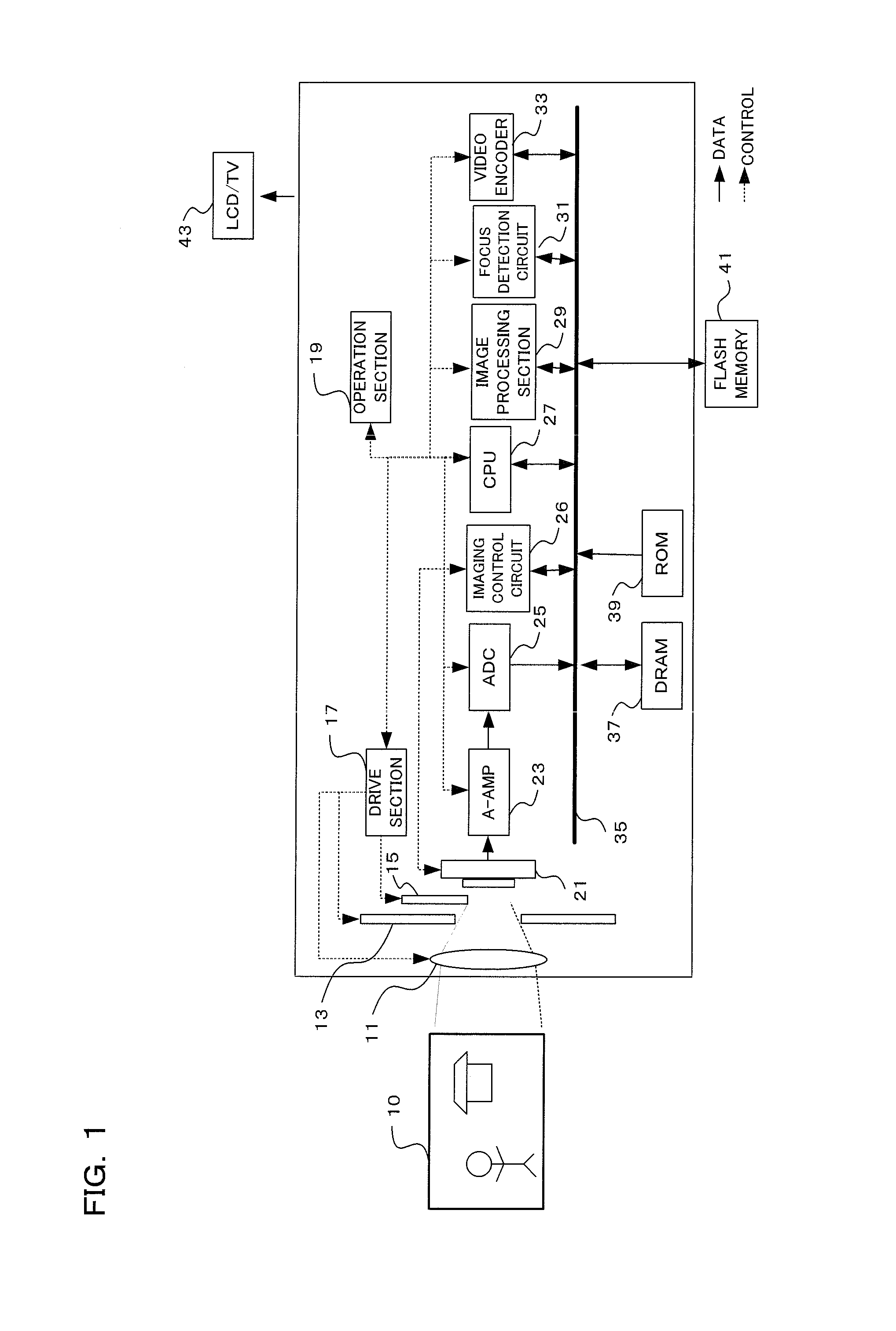
[0020]Preferred embodiments using a camera to which the present invention has been applied will be described in the following in accordance with the drawings. The camera of one embodiment of the present invention is a digital camera, provided with an imaging section having an image sensor that comprises phase difference pixels for focus detection using a phase difference detection method in some of the image in pixels, with a subject image being converted to image data by this imaging section, and focusing of a photographing lens being performed by calculating defocus direction and defocus amount using a well-known phase difference detection method based on output from the phase difference pixels.

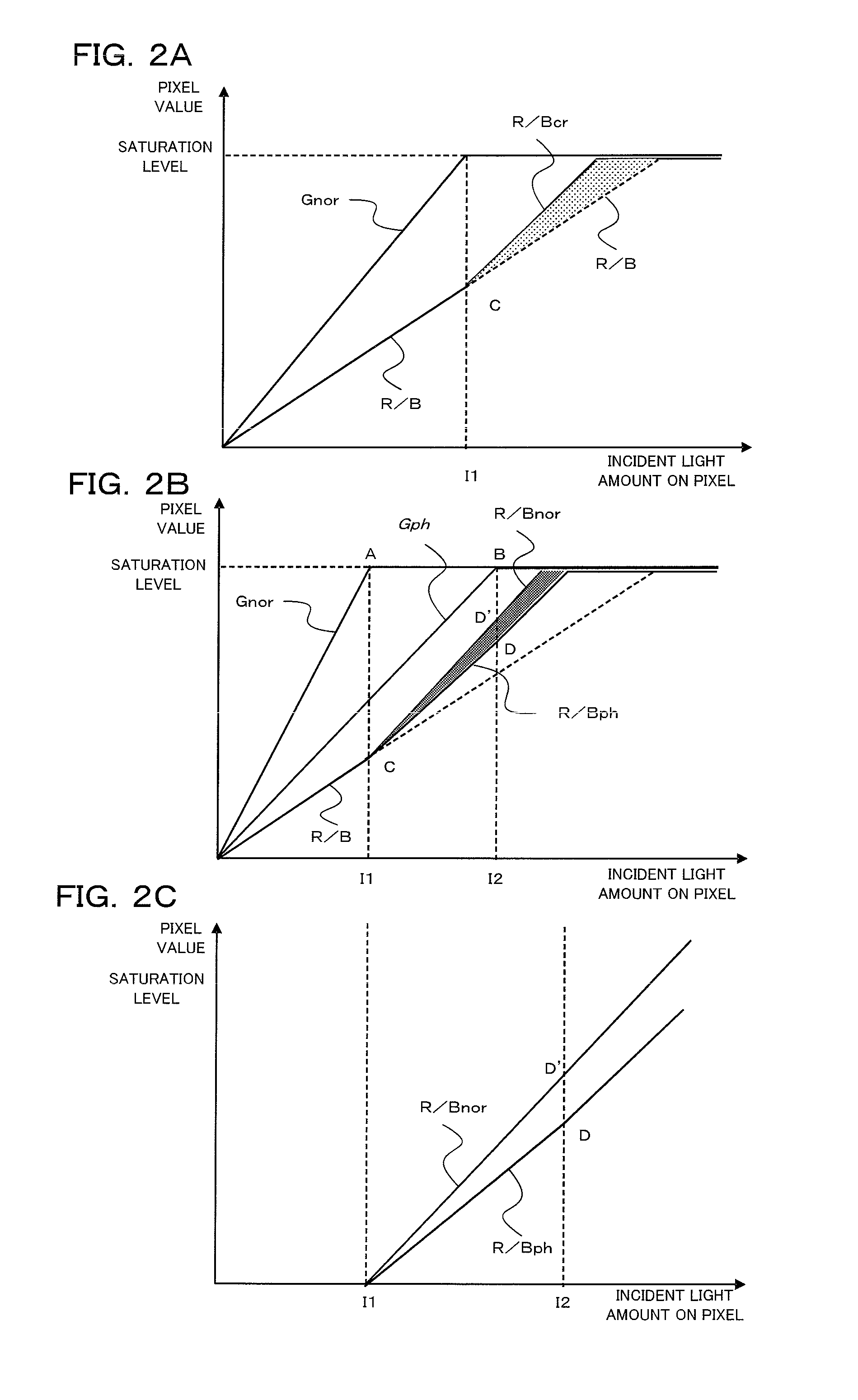
[0021]Also, live view display is carried out based on image data that has been generated by the images section, and still image shooting and movie shooting are carried out. At this time, crosstalk difference amount for respective pixel values is estimated from pixel values of pixels that ha...


PUM


Abstract

An image processing device of the present invention comprises an image sensor having phase difference detection pixels for focus detection arranged at positions of some imaging pixels, a crosstalk effect level estimating section for estimating crosstalk effect level for respective pixel values, from pixel values of pixels that are subject to the effects of crosstalk from the phase difference detection pixels, and pixel values of nearby pixels that are not subject to the effect of crosstalk from the phase difference detection pixels, and a correction processing section for correcting pixel values of pixels that have been affected by crosstalk from the phase difference detection pixels based on the crosstalk effect level that has been estimated by the crosstalk effect level estimating section.

Description

[0001]Benefit is claimed, under 35 U.S.C. §119, to the filing date of prior Japanese Patent Application No. 2013-107069 filed on May 21, 2013. This application is expressly incorporated herein by reference. The scope of the present invention is not limited to any requirements of the specific embodiments described in the application.BACKGROUND OF THE INVENTION[0002]1. Field of the Invention[0003]The present invention relates to an image processing device and an image processing method capable of reducing differences in color between regions where normal pixels are arranged and regions where phase difference pixels are arranged.[0004]2. Description of the Related Art[0005]Technology used in auto focus, where phase difference pixels for detecting phase difference are arranged on part of an image sensor, phase difference information is acquired from these phase difference pixels, and a defocus amount for an imaging optical system is calculated, is commonplace. On the other hand, as a ge...

Claims


Application Information

Patent Timeline
Patent Type & Authority Applications(United States)
IPC IPC(8): H04N9/04H04N23/12
CPCH04N9/045H04N23/672H04N25/62H04N25/704H04N23/843H04N25/134
Inventor TOYODA, TETSUYA
Owner OLYMPUS CORP
Learn More