
Hierarchical Network Managers

a network manager and hierarchy technology, applied in the field of hierarchy network managers, can solve the problems of restricting imposing a limit on the number of machines that can communicate over a single virtual network, and too small a number on its own

Active Publication Date: 2014-11-27
NICIRA
View PDF4 Cites 51 Cited by
  • Summary
  • Abstract
  • Description
  • Claims
  • Application Information

AI Technical Summary

Benefits of technology

The patent describes a network management system for a hosting system that allows for the creation and maintenance of logical networks. The system includes local domain management servers and a second level management server for coordinating the creation of logical networks. The system allows for the allocation of network identifiers to logical networks and the creation of ports for virtual machines connected to the logical networks. The second level management server regularly performs status polling and allows for the addition or removal of virtual machines and domains from the logical network. The system also allows for the analysis and update of logical networks through the use of logical network identifiers. Overall, the system provides an efficient and flexible way to manage logical networks in a hosting system.

Problems solved by technology

A hosting system architecture may have various constraints on how virtual machines within the hosting system can be linked together in a network.
For instance, some technologies impose a limit on the number of machines that can communicate over a single virtual network, or the number of virtual networks possible on a single physical network.
With the growing prevalence of data center usage, this is too small a number on its own.
Furthermore, the technologies in some hosting systems may restrict the number of machines that can communicate with each other over one virtual network.
However, with larger and larger networks required, a tenant may need a network that covers multiple pods.
Without coordination between the pods, setting up a virtual network with machines in both pods will be difficult.

Method used


Image

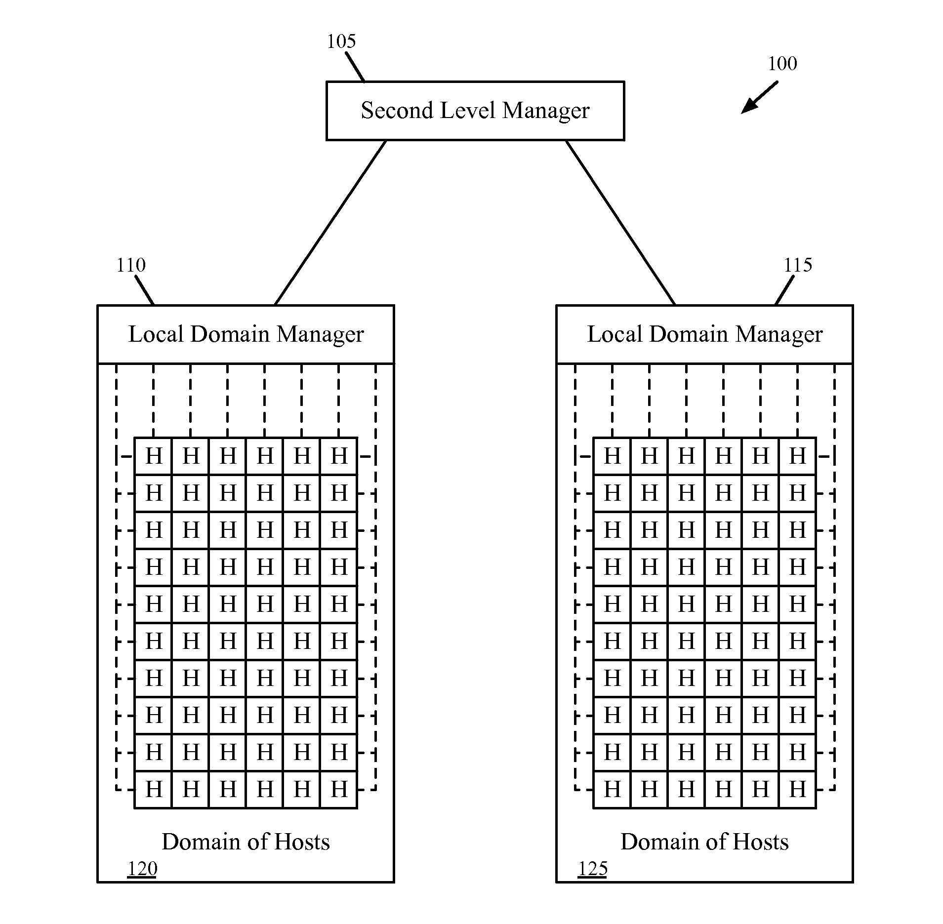
  • Hierarchical Network Managers
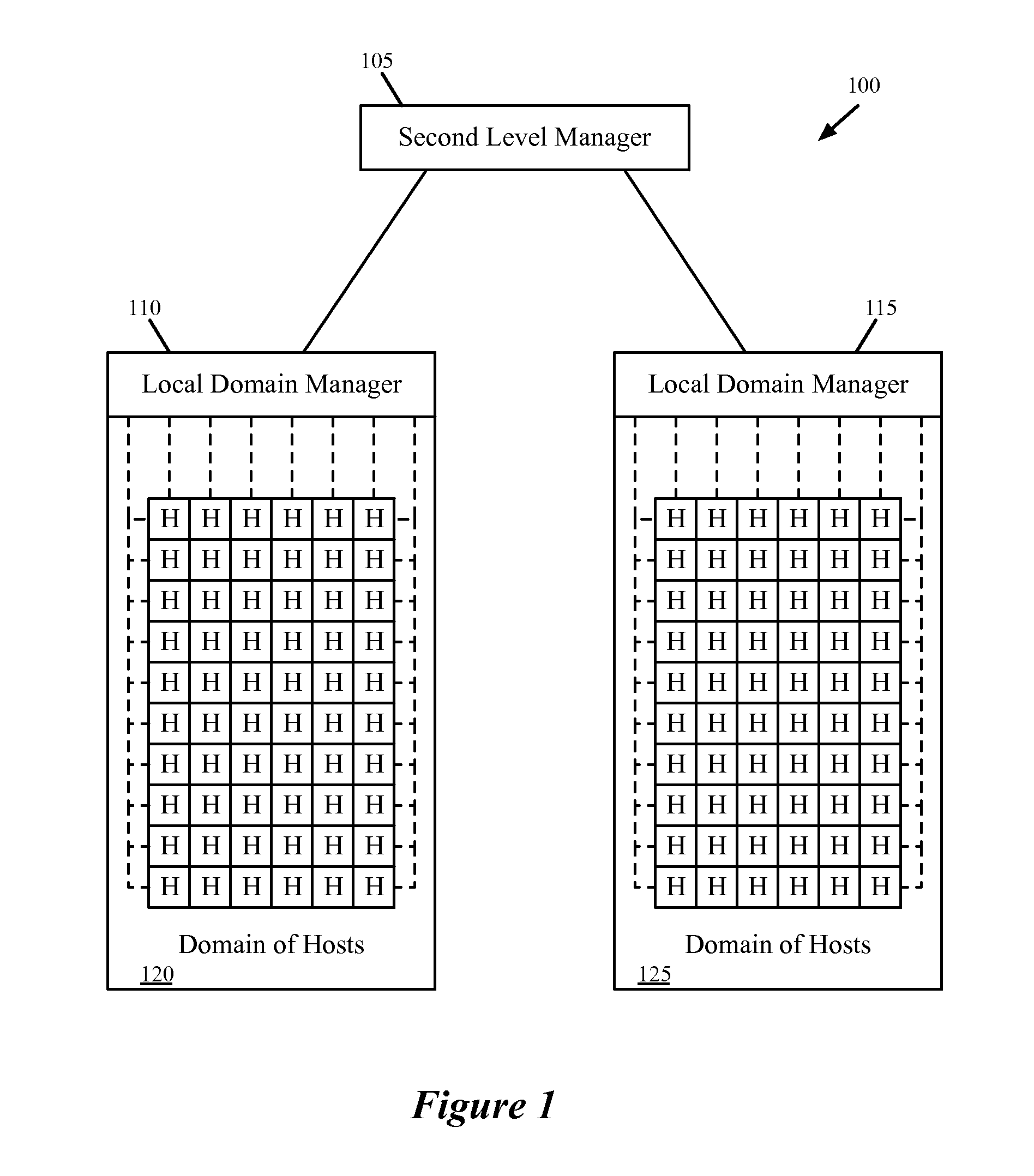
  • Hierarchical Network Managers
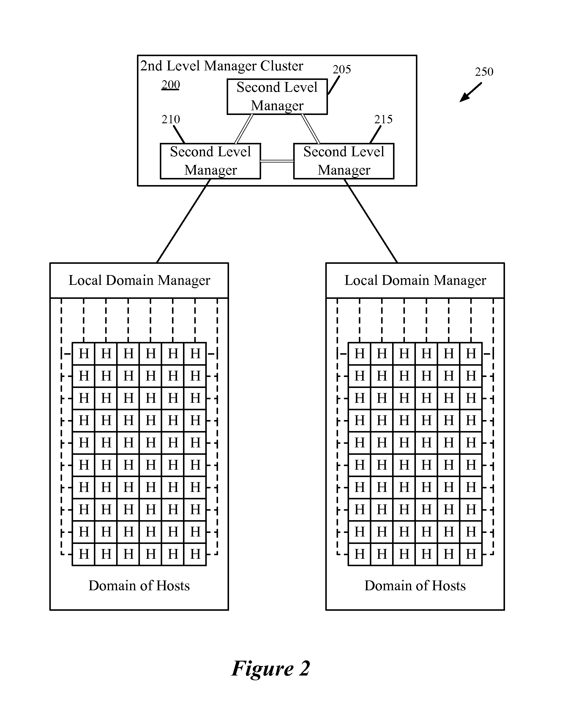
  • Hierarchical Network Managers

Examples


Embodiment Construction

[0027]In the following detailed description of the invention, numerous details, examples, and embodiments of the invention are set forth and described. However, it will be clear and apparent to one skilled in the art that the invention is not limited to the embodiments set forth and that the invention may be practiced without some of the specific details and examples discussed.

[0028]Some embodiments provide a network management system for a hosting system that includes local domain management servers at each of several domains within the hosting system and a second level management server for coordinating creation and maintenance of logical networks by the local domain management servers. The hosting system, in some embodiments, includes numerous host machines divided into several domains, each of which has a local domain management server. When the second level management server receives a specification of a logical network that spans one or more domains, the second level server al...


PUM


Abstract

Some embodiments provide a network system that includes several host machines for hosting virtual machines, divided into several different domains. The network system includes several local domain management servers. A first local domain management server of a first domain is for (i) initiating creation of a set of distributed virtual switch ports associated with a particular logical network identifier on a host machine within its domain and (ii) attaching a first virtual machine on the host machine to a created port associated with the particular logical network identifier in order for the first virtual machine to send traffic over the logical network. The network system includes a second level management server for coordinating the use of logical network identifiers between multiple different logical domain management servers in order for the first virtual machine to communicate via the logical network with a second virtual machine in a second domain.

Description

BACKGROUND[0001]A hosting system architecture may have various constraints on how virtual machines within the hosting system can be linked together in a network. For instance, some technologies impose a limit on the number of machines that can communicate over a single virtual network, or the number of virtual networks possible on a single physical network. VLAN technology, for example, can only have 4,094 different virtual networks on a single network. With the growing prevalence of data center usage, this is too small a number on its own. As a result, various technologies have appeared to augment or replace the standard VLAN tagging within a multi-tenant hosting system.[0002]Furthermore, the technologies in some hosting systems may restrict the number of machines that can communicate with each other over one virtual network. For example, a data center might be divided into numerous separate “pods”, each separately managed. However, with larger and larger networks required, a tenan...

Claims


Application Information

Patent Timeline
IPC IPC(8): H04L12/24
CPCH04L41/044H04L43/0817H04L43/10H04L51/04G06F9/45558H04L67/10H04L45/04H04L65/40H04L2101/622H04L41/12H04L67/1095
Inventor STABILE, JAMES JOSEPHBASAK, DEBASHISPALSHIKAR, AMOLTHAKKAR, SACHIN
Owner NICIRA
Learn More