Protective Base Lens

a protective base and lens technology, applied in the field of protective lenses, can solve the problems of user's vision being obstructed, injury to sporting participants or workers, or to others, and the cleaning method is usually not desirabl

Inactive Publication Date: 2014-12-04
ONEAL JR DAVID L +1
View PDF3 Cites 7 Cited by
  • Summary
  • Abstract
  • Description
  • Claims
  • Application Information

AI Technical Summary

Benefits of technology

[0018]It is a further aspect of at least one of the present embodiments wherein the circular flanged ends of the post member fasteners being d

Problems solved by technology

Although the visor or face shield provides protection to the user's face and eyes, the user's vision may become obstructed due to the accumulation of dirt and such other debris on the outer surface of the face shield or visor.
An obstructed field of vision for the participant of a sporting event, or a worker at his or her place of employment, is unsafe and may result in injury to the sporting participant or the worker, or to others due to the unsafe actions of the sporting participant or worker.
Although a visor or face shield can be manually cleaned, this cleaning method is usually not desirable due to the time required for such cleaning, as well as the interruption to the

Method used


Image

  • Protective Base Lens
  • Protective Base Lens
  • Protective Base Lens

Examples


Embodiment Construction

[0030]Reference will now be made in detail to the embodiments of the invention, one or more examples of which are set forth below. Each example is provided by way of explanation of the invention, not limitation of the invention. In fact, it will be apparent to those skilled in the art that various modifications and variations can be made in the present invention without departing from the scope or spirit of the invention. For instance, features illustrated or described as part of one embodiment can be used on another embodiment to yield a still further embodiment. Thus, it is intended that the present invention cover such modifications and variations as come within the scope of the appended claims and their equivalents. Other objects, features, and aspects of the present invention are disclosed in the following detailed description. It is to be understood by one of ordinary skill in the art that the present discussion is a description of exemplary embodiments only and is not intende...


PUM


Abstract

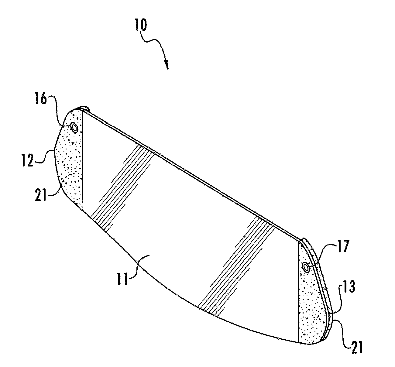
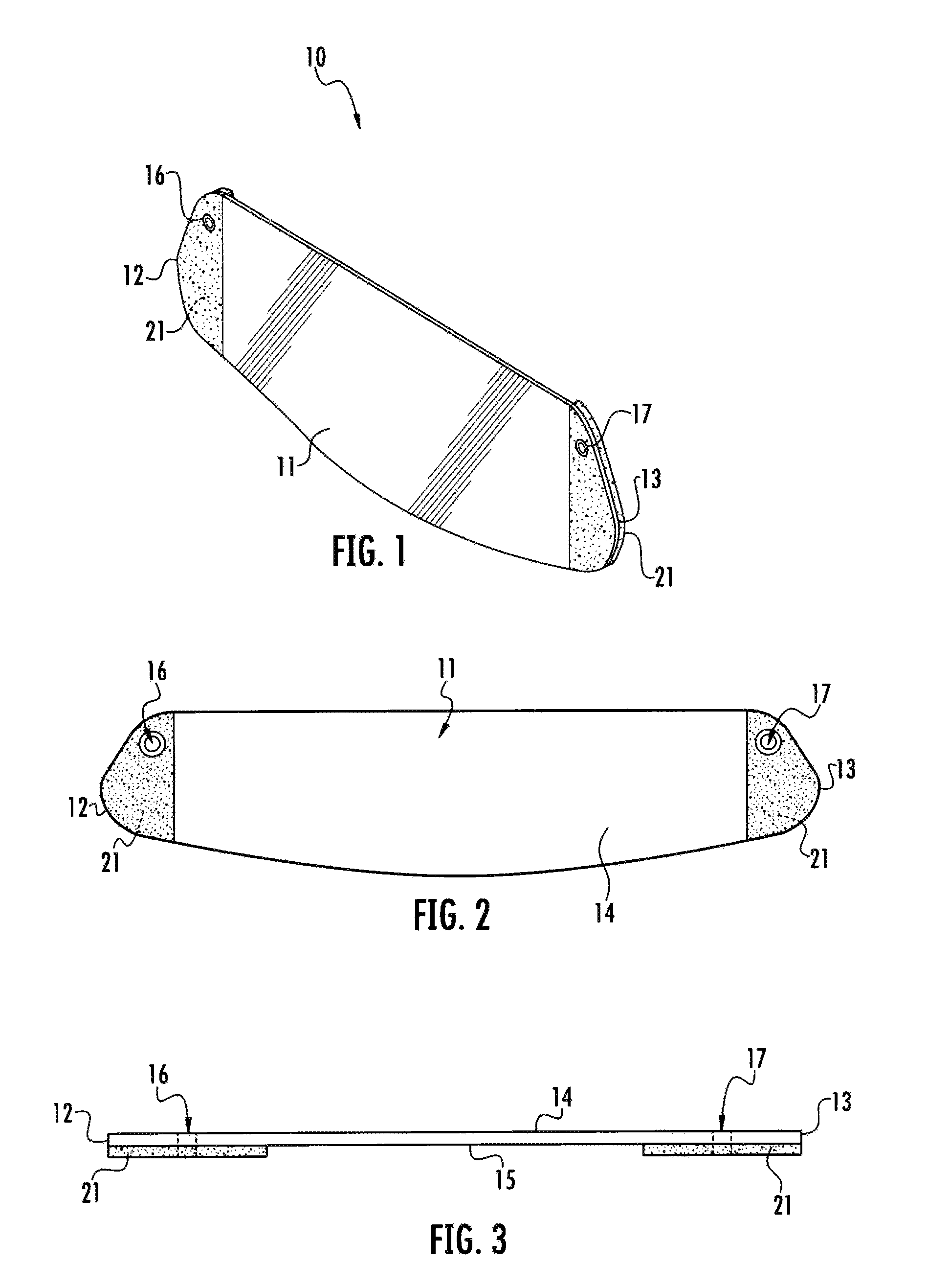
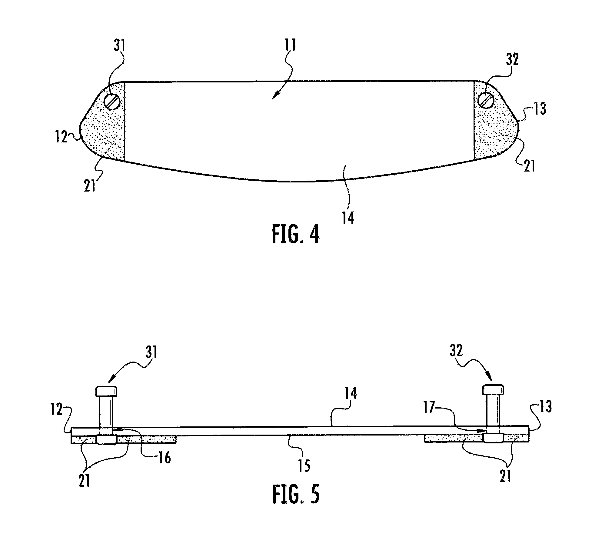
A protective base lens configured for attachment to the visor or face shield of a helmet upon which protective tear-away lenses may be mounted. The protective base lens includes an elongated flexible clear transparent sheet with apertures at each end with post member fasteners being reversibly secured within the apertures. A pressure sensitive adhesive is affixed to the bottom surface at each end of the transparent sheet to attach the protective base lens to the helmet visor. One or more tear-away lenses operationally engage the post member fasteners and are reversibly mounted to the top surface of the transparent sheet. The protective base lens being designed and configured to be used with or without tear-away protective lenses.

Description

RELATED APPLICATIONS[0001]This application claims benefit of U.S. Application Ser. No. 61 / 830,573 filed on Jun. 3, 2013, and which is incorporated herein by reference.STATEMENT AS TO RIGHTS TO INVENTIONS MADE UNDER FEDERALLY SPONSORED RESEARCH AND DEVELOPMENT[0002]Not Applicable.PARTIES TO A JOINT RESEARCH AGREEMENT[0003]Not Applicable.SEQUENCE LISTING[0004]Not Applicable.FIELD OF THE INVENTION[0005]The present invention relates to the field of protective lens for helmet visors or face shields and to the mounting of tear-away lenses onto such helmet visors or face shields.BACKGROUND OF THE INVENTION[0006]The need to protect a person's face and eyes in the work place and during sporting events is well known and devices to provide such protection exist is various forms and formats. Various sporting activities and occupations employ a protective helmet with a visor or face shield. Although the visor or face shield provides protection to the user's face and eyes, the user's vision may b...

Claims


Application Information

Patent Timeline
IPC IPC(8): A42B3/26
CPCA42B3/26
Inventor O'NEAL, JR., DAVID L.FERGUSON, JR., ANTHONY R.
Owner ONEAL JR DAVID L
Why Eureka
Try Eureka